Excel 500/600 CONTROL SYSTEM INSTALLATION INSTRUCTIONS CONTENTS Revision Overview ........................................................................................................................................................................ 4 Safety Instructions ....................................................................................................................................................................... 5 MOUNTING ...........................................................
EXCEL 500/600 INSTALLATION INSTRUCTIONS Line Power Supply ............................................................................................. 23 XC6010 Computer Module................................................................................. 23 XC5010C Computer Module .............................................................................. 24 XP502 Power Supply Module.............................................................................
EXCEL 500/600 INSTALLATION INSTRUCTIONS GSM Antenna Installation ....................................................................................... 47 M20 Terminal Set-up...............................................................................................
EXCEL 500/600 INSTALLATION INSTRUCTIONS REVISION OVERVIEW On the following pages, changes have been made compared to the previous release of this document: Page: throughout 21 23 27 30 34 EN1R-1047GE51 R0902 Change: Information regarding Distributed I/O modules has been removed. Please refer instead to Distributed I/O Product Data (EN0B-0090GE51). Fig. 44 has been changed. Fig. 45 has been changed.
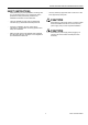
EXCEL 500/600 INSTALLATION INSTRUCTIONS SAFETY INSTRUCTIONS — When performing any work (installation, mounting, startup), all instructions given by the manufacturer and in particular the safety instructions provided in the Installation Instructions are to be observed. — The Excel 500/600 controller may be installed and mounted only by authorized and trained personnel. — If the unit is modified in any way, except by the manufacturer, all warranties concerning operation and safety are invalidated.
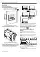
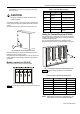
EXCEL 500/600 INSTALLATION INSTRUCTIONS MOUNTING Control Unit Installation The Excel 500 and 600 controllers have the same housing and can be installed two different ways: — Installation inside a control panel (see page 8). — Installation through a control panel door (see page 10). Fig. 3. Up to five housings can be connected together When housings are alongside one another, a minimum spacing of 1.5 in. (35 mm) should be taken into consideration to enable the hinged cover to be opened.
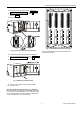
EXCEL 500/600 INSTALLATION INSTRUCTIONS — Table 1. Internal module locations Type XW569 13 in. (330 mm) long (for housings one above the other) Module Type Module location CAUTION CPU XC5010C / XC6010 1 housing, location 4 Incorrectly inserted bus cables can destroy the modules installed.
EXCEL 500/600 INSTALLATION INSTRUCTIONS CAUTION Setting the Module Address (not XCL5010) Unplugging a module before switching OFF the power supply could destroy the module. Do not unplug modules with the power still connected. First switch S1 on the power supply module to the 0 position. In the case of application prior to CARE 4.0, you can set the module address using the rotary HEX switches located on the upper surface of the respective input and output modules.
EXCEL 500/600 INSTALLATION INSTRUCTIONS 3. Code the terminal block (see section "Coding the Terminal Block (not XCL5010)" on page 7). 4. Make sure that the locking screws are positioned as shown in Fig. 13. 5. Plug in the enclosure. Fig. 15. Excel 500/600 extended wiring base Fig. 13. Housing locking screws and latches Using the extended wiring base the I/O terminals are accessible at run-time. 6. Shift latches inwards until the housing is released. 7.
EXCEL 500/600 INSTALLATION INSTRUCTIONS Excel 500-XCL5010 Plug in the communication module until it snaps into the con troller housing 1. Attach the DIN rail mounting clips to the housing. 2. Mount the controller on the DIN rail. 0000079a NOTE: If the communication module has been replaced or pulled out and plugged in again, push the reset button after power on. 1 Installation through a Control Panel Door (not XCL5010) IMPORTANT Observer the minimum spacing of 1.5 in.
EXCEL 500/600 INSTALLATION INSTRUCTIONS External Installation of XI582AH Operator Interface 1. Remove the cover. Fig. 23. Loosening the cover Fig. 20. Housing retaining clamp 4. Turn retaining clamp to fix housing. 5. Code the terminal block (see page 7). 6. Install the base. Fig. 21. Installing the wiring base Fig. 24. Removing cover 7. Complete electrical wiring. 8. Lock the cover. 2. If mounting on a wall, disconnect cable from panel for easier handling. Fig. 25. Disconnecting cable from cover 3.
EXCEL 500/600 INSTALLATION INSTRUCTIONS Fig. 26. Routing the cable Fig. 29. Making electrical connections 4. If mounting on a wall, remove feet. 8. Reattach the cover. Fig. 27. Removing feet Fig. 30. Reattaching cover 5. Attach the housing to the wall. Deactivating Backlit Display of the XI582AH The XI582AH Operator Interface is equipped with an integrated backlit display to suit the display to the ambient lighting conditions. By default, this backlight is ON.
EXCEL 500/600 INSTALLATION INSTRUCTIONS Fig. 32. Backlight OFF jumper position When the jumper is disabled (OFF-position), the backlight is permanently deactivated. The contrast of the display can be adjusted using the potentiometer at the rear of the unit. Fig. 31. Jumper location (backlight ON position) The figure above shows the location of the jumper. To change jumper position, disconnect the connector first, then pull off jumper with tweezers or pincers and move to new position.
EXCEL 500/600 INSTALLATION INSTRUCTIONS Dimensions Excel 500/600 Fig. 34.
EXCEL 500/600 INSTALLATION INSTRUCTIONS Excel 500-XCL5010 Fig. 35.
EXCEL 500/600 INSTALLATION INSTRUCTIONS XI582AH Fig. 36.
EXCEL 500/600 INSTALLATION INSTRUCTIONS Battery Activation during Commissioning (XC6010, only) The controller is delivered from the factory with the battery in the computer module electrically isolated from the internal circuitry by a safety tag to prevent the battery from discharging in transit. The controller is delivered from the factory with the battery in the computer module electrically isolated from the internal circuitry by a safety tag to prevent the battery from discharging in transit. 1.
EXCEL 500/600 INSTALLATION INSTRUCTIONS NOTE: The CPU modules XC5010C and XCL5010 do not contain a battery. RAM is buffered for 3 days by a capacitor. Dismantling the Control Panel Unit Before dismantling the controller, the low voltage switch S1 of the power supply module must be switched OFF (position 0). To dismantle the control panel unit, reverse the steps of the installation procedure (see page 8).
EXCEL 500/600 INSTALLATION INSTRUCTIONS Dismantling the XI582AH Operator Interface 2 Use a pencil or similar object to open the XI582AH Operator Interface. 2 1 0000079b 1 Fig. 43. Opening the XI582AH Operator Interface unit Fig. 42. Removing Excel 500-XCL5010 from DIN rail 1. Dismantle the controller housing as depicted. 2. Pull the lower part of the housing off the control panel. 3. Lift the housing from DIN rail.
EXCEL 500/600 INSTALLATION INSTRUCTIONS ELECTRICAL CONNECTIONS Shielding of Data-Transmitting Cables When connecting the controller, both VDE, National Electric Code NEC (or equivalent) and any local regulations con cerning grounding and zero voltage must be observed. Electrical work should be carried out by a qualified electrician. Under no circumstances should spare controller terminals be used as wiring support points. Doing so could damage the modules.
EXCEL 500/600 INSTALLATION INSTRUCTIONS XC5010C / XC6010 Cable Lengths and Sizes A cable length of 1300 ft (400m) with a cross sectional area of 2 0.5 mm (20 AWG) is permissible for a two-core, 0 to 10 Vdc signal cable. Table 3. Cable sizing Cross sectional area Type of signal 24 Vac power supply ≤ 550 ft (170 m) ≤ 1300 ft (400 m) ≤ 16 AWG 2 (≥ 1.5 mm ) ≤ 14 AWG 2 (≥ 2.5 mm ) - Lightning Protection Please contact your local Honeywell representative for information on lightning protection.
EXCEL 500/600 INSTALLATION INSTRUCTIONS Summary of Internal Modules Table 4.
EXCEL 500/600 INSTALLATION INSTRUCTIONS Line Power Supply Table 5. 1450 series transformers data Part # 1450 7287 -001 WARNING -002 A separate CRT 6 or 1450 series (U.S.) transformer must be used for each of the EXCEL 500/600 controller's 24 V supply. No additional loads may be connected ! Each additional XL500/600 controller requires its own transformer. An additional transformer, appropriate to the power require ments, should be used to power input/output peripherals (e.g. actuators).
EXCEL 500/600 INSTALLATION INSTRUCTIONS Fig. 50. Excel 600 submodule mounting location For information pertaining to system bus baud rates and termination switch settings, see section "C-Bus Termination (Excel 600)" on page 38. Fig. 48. Excel 600 CPU modem connection XC5010C Computer Module The XC6010 has 2 EPROMs for the operating system and one flash EPROM for the application software. Their locations are shown in Fig. 49.
EXCEL 500/600 INSTALLATION INSTRUCTIONS XP502 Power Supply Module NOTE: Shielded cable is not necessary for the LONW ORKS bus. Fig. 53 shows the pin-out of the XP502 Power Supply module. The serial port connections at the back of the module can be used to connect an XI582 MMI or, for CPUs with firmware version V2.1.0 or newer, a modem or ISDN terminal adapter. See section "Remote Communications" on page 43 for more information.
EXCEL 500/600 INSTALLATION INSTRUCTIONS Fig. 54. Connection of XAPU 24-2F UPS (internal modules) LED (L3) shows operation by battery. NOTE: The output from the XAPU 24-2F must not be connected with other devices. The fully-equipped Excel 500/600 controller will be completely supported with the battery for at least 15 minutes, without the mains power 230 Vac. Fig. 55.
EXCEL 500/600 INSTALLATION INSTRUCTIONS XP502 with External UPS XAPU 24-2F (Distributed I/O and Internal Modules) XF521A Analog Input Module As shown in the figure below, two XAPU 24-2F UPSs are required when the controller has both internal and Distributed I/O modules connected. Number: eight inputs (AI1 – AI8) Input: 0...10 Vdc (low-input impedance, 25kOhm to 10 V / 200kOhm to GND); 0...20 mA (via external 500-ohm resistor); 4...20 mA (via external 500-ohm resistor); NTC 20K ohm (-50...
EXCEL 500/600 INSTALLATION INSTRUCTIONS XF526 Analog Input Module Fig. 58 shows several connection examples for various sensors: WS21 Wind Sensor; SAF 25 Solar Sensor; and VMP Feedback Potentiometer. Technical Specifications Number: eight inputs (AI1 – AI8) Input: 0...10 Vdc (low-input impedance, 25kOhm to 10 V / 200kOhm to GND); 0...20 mA (via external 500-ohm resistor); 4...20 mA (via external 500-ohm resistor); NTC 20K ohm (-50...+150 °C); PT1000 (-50...+150 °C) PT1000 (0...+400 °C) PT100 (-50...
EXCEL 500/600 INSTALLATION INSTRUCTIONS Fig. 61. Digital input hysteresis The LED functionality of each digital input channel can be altered via 12 internal DIP switches. In the ON position (default), the LED will illuminate when energized (normally open contacts). In the OFF position, the LED will illuminate when de-energized (normally closed contacts). Max. signal voltage from non-Honeywell voltage sources: DC Voltage: Vmax = 40 V AC Voltage: Vmax = 28 V / ≥ 50 Hz Input resistance: Ri = 15k ohms Fig.
EXCEL 500/600 INSTALLATION INSTRUCTIONS XF522A and XF527 Analog Output Modules XF524A and XF529 Digital Output Modules Technical Specifications Technical Specifications Number: 8 analog outputs Voltage rating: 0 to 10 V, max. 11V Current rating: 1 mA max. Resolution: 8 bit Accuracy: ±150 mV or 1.5% deviation from output voltage Number: 6 digital outputs Voltage rating: 240 Vac max. per contact and per module Current rating: 4 A max. per contact, 12A max.
EXCEL 500/600 INSTALLATION INSTRUCTIONS XF525A Three-Position Output Module An L 16 miniature circuit breaker or G 10 A quick blow fuse should be used to protect the 240 Vac mains supply. Technical Specifications Voltage rating: 240 Vac or 28 Vdc max. Current rating: 0.2A max. at 240 Vac 1.2A max. at 28 Vdc NOTE: The maximum voltage for the U.S. is 24 V. Fig. 65.
EXCEL 500/600 INSTALLATION INSTRUCTIONS Excel 500-XCL5010 The Excel 500-XCL5010 housing comprises a removable screw terminal block for direct power supply wiring. For proper installation of the terminal block, follow these instructions: 1. Read the complete chapter "Installation" carefully. 2. Follow the instructions from the chapter Screw Terminal Block Installation Procedure on page 33. Table 11.
EXCEL 500/600 INSTALLATION INSTRUCTIONS Table 13. 1450 Series transformers Fig. 69. Transformer example Use quick-acting backup fuse 10 A (or automatic H16 or L16) to protect transformer primary side. On the primary side of the CRT 2, there is a fusible output of type M 0.315 A (T) 250 V for the purpose of fine fusing.
EXCEL 500/600 INSTALLATION INSTRUCTIONS 4. Select one of the transformers of the CRT-series or 1450 series from the tables on the previous page or take a commercially available standard transformer fulfilling the requirements listed in Table 14. 5. Make sure that the communication module is attached to the controller housing. IMPORTANT The transformer feeding the Excel 500 Controller must be in the same cabinet. For the selection of the transformer, the max.
EXCEL 500/600 INSTALLATION INSTRUCTIONS 10 Vdc Immersion temperature sensor VF 100 Air duct temperature sensor LF 100 Wind sensor: Wind sensor WS21. Further connections: Temperature sensor terminal TF26 25K ohm Vi 200K ohm Table 15. Accuracy of analog input sensors ground Fig. 75. Analog input / low-impedance sensors Range Pt1000 Pull-Up Resistor Handling when Using Analog Inputs as Digital Inputs (O.S. 2.03.
EXCEL 500/600 INSTALLATION INSTRUCTIONS COMMUNICATIONS LONWORKS Bus Wiring IMPORTANT Do not use different wire types or gauges on the same LONWORKS network segment. The step change in line impedance characteristics would cause unpredictable reflections on the bus.
EXCEL 500/600 INSTALLATION INSTRUCTIONS Submodule Selection (XC6010) Two submodules for system bus communication are available. The selection depends on the communication speed. Table 18. C-Bus submodule baud rates Fig. 80.
EXCEL 500/600 INSTALLATION INSTRUCTIONS Inside the cabinet: J-Y-(ST)Y 2 x 2 x 0.8 Outside the cabinet: A-Y-(ST) 2 x 2 x 0.8 The XD508 submodule is equipped with a DIP switch which activates (ON position) deactivates (OFF position) a terminating resistor. Depending on where the controller is located on the bus the DIP switch settings must be as follows: Table 21. XD508 DIP switch settings for C-Bus termination In principle, data transmitting cables should be shielded in case of RFI.
EXCEL 500/600 INSTALLATION INSTRUCTIONS For connection to the XI584 Operator and Service Computer, a tailor-made cable is available with plugs on both ends. — XW567 cable, length 7 ft (2.5m) Fig. 84. Excel 500-XCL5010 C-Bus DIP switch location Table 23. DIP switch settings for C-Bus termination (Excel 500-XCL5010) DIP switch setting Communication speed up max. 9.6 Kbaud middle max. 76.8 Kbaud down max. 76.
EXCEL 500/600 INSTALLATION INSTRUCTIONS Excel 500 Cable Specifications The XI582AH Operator Interface can be connected either to the or the back of the XC5010C. — XW582 cable, front connection, length 15 ft (5 m) — XW583 cable, back connection, length 15 ft (5 m) Fig. 88. Excel 500 / XI584 operator and service computer cable details NOTE: You can also use a standard null modem cable.
EXCEL 500/600 INSTALLATION INSTRUCTIONS Excel 500-XCL5010 Cable Specifications MMI Cables Modem or ISDN Terminal Adapter Connections Ready-made cables with the shield already connected to the computer module plug end are available for the connection of external MMIs. For remote communications, a modem or ISDN terminal adapter can be connected directly to the serial port of the Excel 500-XCL5010 Controller.
EXCEL 500/600 INSTALLATION INSTRUCTIONS Fig. 90. Excel 500 and Excel 600 used together with XI584 and XI582 Operator Interfaces Fig. 91.
EXCEL 500/600 INSTALLATION INSTRUCTIONS REMOTE COMMUNICATIONS The following applies to the XC5010C and XCL5010, only. For remote communications with up to three XBS Building Centrals, a modem or ISDN terminal adapter can be connected directly to the serial port of the XC5010C CPU (either front or rear connection) or the serial port of the XCL5010. The serial port of the XCL5010 CPU accepts a standard modem cable with a female 9-pin connector.
EXCEL 500/600 INSTALLATION INSTRUCTIONS Automatic Baudrate Synchronization The default communication speed between the XC5010C/XCL5010 CPU and the local modem/ISDN terminal adapter is 9600 baud. without waiting for a public network dial tone. Save this modem set-up in the modem EEPROM with the command AT&W. Check the modem handbook to verify the correct commands. Note that these commands are executed automatically with the RESET MODEM command.
EXCEL 500/600 INSTALLATION INSTRUCTIONS modem connected to the Excel controller serial port, and it then transmits via GSM like a cellular (mobile) phone. NOTE: Communication via GSM requires firmware version V2.3.0 or higher. address all questions to a doctor or the manufacturer of the medical device. • The M20 Terminal shall not be used within wet environment, such as in public baths. IMPORTANT With the M20T, data communication is possible only in 900 MHz GSM networks.
EXCEL 500/600 INSTALLATION INSTRUCTIONS Antenna Examples Protection fuse 1 A, fast blow Max. RF power 2 W at 900 MHz Power supply connector 6-pin modular CE conformity: • 89/336/EC (EMC guideline) • 73/23/EC (Low voltage guideline) • 91/263/EC (Telecommunications devices guideline) Standards: • EMC: ETS 300 342-1 • Safety: EN 60950 • GSM network: TBR 19, TBR 20 Serial Cable For connecting the M20T to the Excel 500 controller, a standard RS232 cable (9-pin V24 sub-D sockets) is required.
EXCEL 500/600 INSTALLATION INSTRUCTIONS GSM Antenna Installation M20 Terminal Set-up The maximum antenna cable length is 8.0m (including the 20 cm M20 Terminal cable). Use a cable that is specified by the supplier of the GSM antenna. Improper cables with resistances that are too high will reduce the amplification of the antenna. Prior to beginning the set-up, get the M20T manual (or CDROM, if it was delivered with one). Everything is described in it and you will need it.
EXCEL 500/600 INSTALLATION INSTRUCTIONS NOTE: As soon as the PIN is entered into the Excel controller, the following mechanisms will take place automatically: — Cyclical check (once per minute) for existence of the PIN number in the M20 (AT+CPIN?) — Sending of PIN number to M20T, if it has lost it. This guarantees communication will resume automatically after exchange of the SIM card or after power to the M20T has been lost.