
Installation Instructions

7
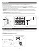
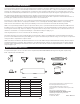
FINAL INSTALLATION
Figure 5.5
Figure 5.8 Figure 5.9
Figure 5.4
Figure 5.7
Figure 5.6
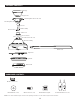
Blade Screw
Glass Bowl
Light Pull Chain
Fan Pull Chain
Reverse Switch
Blade Washer
Fitter Plate Screw
Light Pan
Light Pan Screw
Light Kit
9-pin
Connector
Blade
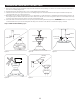
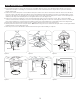
4. Insert blade through slot in the side of the motor assembly. Align the holes of one blade with three blade screw holes in
underside of the motor assembly. Secure with three blade screws and blade washers. Repeat this step for the remaining
blades (Figure 5.4).
5. Remove one of the tter plate screws from the tter plate, and loosen (do not remove) the other two. Then, insert the wires
from the center of the fitter plate through the hole in the light pan. Align the light pan over the loosened fitter plate screws,
then place the keyholes of the light pan onto the fitter plate screws and rotate the light pan clockwise. Secure the light pan
with the previously removed tter plate screw. Tighten all three screws (Figure 5.5).
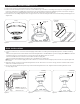
6. Remove one of the three light pan screws from the light pan and loosen the other two screws. Then, connect the 9-pin
connector from the fan to the 9-pin connectors from the light kit. Align the screw holes of the light kit over the loosened light
pan screws and turn in a clockwise direction. Replace previously removed light pan screw. Tighten all screws (Figure 5.6).
7.Lift the glass bowl into the light kit and turn in a clockwise direction until it is secure (Figure 5.7).
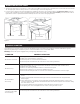
8. Attach pull chain extensions to the pull chains. Note: When facing the reverse switch the fan pull chain is on the right and the
light pull chain is on the left (Figure 5.8).
9. Turn on power to fan at breaker box and the wall switch (Figure 5.9). Assembly is complete.