
Full Product Manual


4
1.1 UNPACKING
• Remove all packaging material.
• Remove the accessory foam pack.
• Remove the generator from the carton.
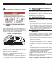
1.1.1 ACCESSORY BOX
Check all contents. If any parts are missing or damaged, locate an
authorized dealer at 1-855-GEN-INFO.
• 1 - Quick Setup Guide
• 1 - Owner’s manual
• 1 - Oil funnel
• 1 - Oil SAE 30
• 3 - Product Registration Cards (English, Spanish, French)
• 2 - 8” Wheels (A)
• 1 - Axle (B)
• 2 - Frame Feet (C)
• 2 - Handles with grips (left (D) and right (E))
• 1 - Hardware Bag
– 4 - M8-1.25 x 43 Bolts (G)
– 4 - M6-1.0 x 37 Step Bolt (I)
– 2 - Cotter Pins (F)
– 4 - M8-1.25 Hex Flange Nuts (H)
– 4 - M6-1.0 Acorn Nuts (J)
1.1.2 REQUIRED TOOLS
• 1- 12 mm box wrench
• 1- Ratchet
• 2- Sockets
– 1- 10 mm socket
– 1- 12 mm socket
1.2 ASSEMBLY
The generator requires some assembly prior to using it. If
problems arise when assembling the generator, please call the
Generator Helpline at
1-855-GEN-INFO.
1.2.1 ASSEMBLING THE ACCESSORY KIT
The wheels are designed to the unit to greatly improve the
portability of the generator.
NOTE:
The wheels are not intended for over-the-road-use.
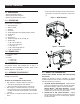
1. Refer to Figure 1 to install the wheels (A) as shown.
– Slide the axle (B) through the frame brackets.
– Slide on the wheels (A) then install the cotter pins (F).
2. Refer to Figure 1 to install the frame feet (C) as shown.
– Place each frame foot (C) under the frame and secure with
two M8-1.25 x 40 bolts (G) and two M8 x 1.25 hex flange
nuts (H).
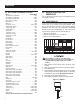
3. Refer to Figure 2 to install the handle assembly (D and E) as
shown.
– Secure each handle assembly (D and E) to the frame using
the two M6-1.0 x 40 bolts (I) and two M6-1.0 acorn nuts
(J).
Figure 1 – Wheel Assembly
Figure 2 – Handle Kit
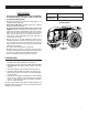
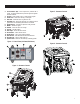
2.1 KNOW THE GENERATOR
Read the Owner’s Manual and Safety Rules before operating
this generator.
Compare the generator to Figures 3 through 6 to become
familiarized with the locations of various controls and adjustments.
Save this manual for future reference.
1. 120 Volt AC, 20 Amp, Duplex Receptacle – Supplies electrical
power for the operation of 120 Volt AC, 20 Amp, single-phase,
60 Hz electrical lighting, appliance, tool and motor loads.
California Models - GFCI Duplex Receptacle – Provides
protection within internal Ground Fault Circuit Interupter
complete with a press to "Test" and "Reset" button.
2. 120/240V AC, 20 Amp Locking Receptacle – Supplies
electrical power for the operation of 120 and/or 240 volt AC,
20 amp, single-phase, 60 Hz, electrical lighting, appliance,
tool and motor loads.
General Information