® AD-54257@
Honeywell Aerospace Electronic Systems CES–Phoenix P.O. Box 21111 Phoenix, Arizona 85036–1111 U.S.A. TO: HOLDERS OF THE PRIMUSR 660 DIGITAL WEATHER RADAR SYSTEM PILOT’S MANUAL, HONEYWELL PUB. NO. A28–1146–111 REVISION NO. 3 DATED AUGUST 2003 HIGHLIGHTS Pages that have been revised are outlined below. Remove and insert the affected pages listed. The revision number has been added to the bottom of the revised pages and revision bars have been used to indicate the revised or added text.
Honeywell Aerospace Electronic Systems CES–Phoenix P.O. Box 21111 Phoenix, Arizona 85036–1111 U.S.A. PRIMUSR 660 Digital Weather Radar System Pilot’s Manual Printed in U.S.A. Pub. No.
PROPRIETARY NOTICE This document and the information disclosed herein are proprietary data of Honeywell. Neither this document nor the information contained herein shall be used, reproduced, or disclosed to others without the written authorization of Honeywell, except to the extent required for installation or maintenance of recipient’s equipment.
PRIMUSR 660 Digital Weather Radar System Record of Revisions Upon receipt of a revision, insert the latest revised pages and dispose of superseded pages. Enter revision number and date, insertion date, and the incorporator’s initials on the Record of Revisions. The typed initials H are used when Honeywell is the incorporator.
PRIMUSR 660 Digital Weather Radar System Record of Temporary Revisions Upon receipt of a temporary revision, insert the yellow temporary revision pages according to the filing instructions on each page. Then, enter the temporary revision number, issue date, and insertion date on this page. Temporary Revision No.
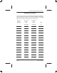
PRIMUSR 660 Digital Weather Radar System List of Effective Pages Original Revision Revision Revision Subheading and Page Revision H Title Page 3 Record of Revisions H RR–1/RR–2 ..0 ..1 ..2 ..3 3 Record of Temporary Revisions RTR–1/RTR–2 0 List of Effective Pages .. .. .. ..
PRIMUSR 660 Digital Weather Radar System Subheading and Page Revision Radar Facts (cont) Subheading and Page Revision Maximum Permissible Exposure Level (MPEL) 5–13 0 5–14 0 5–15 0 5–16 0 5–17 0 7–1 0 0 7–2 0 5–19 0 7–3 0 5–20 0 7–4 0 5–21 0 7–5 0 5–22 0 7–6 0 5–23 0 7–7 0 5–24 0 7–8 0 5–25 0 7–9 0 5–26 0 7–10 0 5–27 0 7–11 0 5–28 0 7–12 0 5–29 0 7–13 0 5–30 0 7–14 0 5–31 0 7–15/7–16 0 5–32 0 5–33 0 5–34 0 5–18 5–35 0 5–36 0
PRIMUSR 660 Digital Weather Radar System Subheading and Page Revision Subheading and Page Revision Appendix A (cont) A–6 0 A–7 0 A–8 0 A–9 0 A–10 0 A–11 0 A–12 0 A–13/A–14 0 Appendix B B–1 1 B–2 1 B–3 1 B–4 1 B–5 1 B–6 1 Index–1 1 Index–2 1 Index–3 1 Index–4 1 Index–5 1 Index–6 1 Index–7 1 Index–8 1 Index A28–1146–111 REV 3 List of Effective Pages LEP–3/(LEP–4 blank)
PRIMUSR 660 Digital Weather Radar System Table of Contents Section Page 1. INTRODUCTION . . . . . . . . . . . . . . . . . . . . . . . . . . . . . 1-1 2. SYSTEM CONFIGURATIONS . . . . . . . . . . . . . . . . . 2-1 3. OPERATING CONTROLS . . . . . . . . . . . . . . . . . . . . 3-1 WI–650/660 Weather Radar Indicator Operation . . . WC–660 Weather Radar Controller Operation . . . . . 3-1 3-10 4. NORMAL OPERATION . . . . . . . . . . . . . . . . . . . . . . . 4-1 Preliminary Control Settings . . . . .
PRIMUSR 660 Digital Weather Radar System Table of Contents (cont) Section Page 5. RADAR FACTS (CONT) Additional Hazards . . . . . . . . . . . . . . . . . . . . . . . . Ground Mapping . . . . . . . . . . . . . . . . . . . . . . . . . . . . . 5-55 5-56 6. MAXIMUM PERMISSIBLE EXPOSURE LEVEL (MPEL) . . . . . . . . . . . . . . . . . . . . . . . . . . . . . . . . . . . . 6-1 7. IN–FLIGHT ADJUSTMENTS . . . . . . . . . . . . . . . . . . 7-1 Pitch and Roll Trim Adjustments . . . . . . . . . . . . . . . .
PRIMUSR 660 Digital Weather Radar System Table of Contents (cont) A FEDERAL AVIATION ADMINISTRATION (FAA) ADVISORY CIRCULARS (CONT) Subject: Thunderstorms . . . . . . . . . . . . . . . . . . . . . . Purpose . . . . . . . . . . . . . . . . . . . . . . . . . . . . . . . . . . Cancellation . . . . . . . . . . . . . . . . . . . . . . . . . . . . . . Related Reading Material . . . . . . . . . . . . . . . . . . . General . . . . . . . . . . . . . . . . . . . . . . . . . . . . . . . . . . Hazards . . . . . . . .
PRIMUSR 660 Digital Weather Radar System Table of Contents (cont) List of Illustrations (cont) Figure Page 5–1 Positional Relationship of an Airplane and Storm Cells Ahead as Displayed on Indicator . . . . . . . . . 5–2 Antenna Beam Slicing Out Cross Section of Storm During Horizontal Scan . . . . . . . . . . . . . . . . . . . . . . 5–3 Sea Returns . . . . . . . . . . . . . . . . . . . . . . . . . . . . . . . . . 5–4 Radar Beam Illumination High Altitude 12–Inch Radiator . . . . . . . . . . . . . . . . .
PRIMUSR 660 Digital Weather Radar System Table of Contents (cont) List of Illustrations (cont) Figure Page 5–32 Probability of Turbulence Presence in a Weather Target . . . . . . . . . . . . . . . . . . . . . . . . . . . . . . . . . . . . . 5–33 Hail Size Probability . . . . . . . . . . . . . . . . . . . . . . . . . . 5–34 Rain Coming From Unseen Dry Hail . . . . . . . . . . . . 5–35 Familiar Hailstorm Patterns . . . . . . . . . . . . . . . . . . . . 5–36 Overshooting a Storm . . . . . . . . . . . . . .
PRIMUSR 660 Digital Weather Radar System Table of Contents (cont) List of Illustrations (cont) Figure Page B–1 EHSI Display Over KPHX Airport With the EGPWS Display . . . . . . . . . . . . . . . . . . . . . . . . . . . . B–2 EGPWS Test Display . . . . . . . . . . . . . . . . . . . . . . . . . B–5 B–6 List of Tables Table Page 2–1 Dual Control Mode Truth Table . . . . . . . . . . . . . . . . . 2–2 PRIMUSR 660 Weather Radar Equipment List . . . . .
PRIMUSR 660 Digital Weather Radar System Table of Contents (cont) List of Tables (cont) Table Page 7–4 Pitch Offset Adjustment Procedure . . . . . . . . . . . . . 7–5 Roll Stabilization (While Turning) Check Procedure . . . . . . . . . . . . . . . . . . . . . . . . . . . . . . . . . 7–6 Roll Gain Adjustment Procedure . . . . . . . . . . . . . . . 7–7 Pitch Stabilization Check Procedure . . . . . . . . . . . . 7–8 Pitch Gain Adjustment Procedure . . . . . . . . . . . . . .
PRIMUSR 660 Digital Weather Radar System 1. Introduction The PRIMUSR 660 Digital Weather Radar System is a lightweight, X–band digital radar with alphanumerics designed for weather detection (WX) and ground mapping (GMAP). The primary purpose of the system is to detect storms along the flightpath and give the pilot a visual indication in color of their rainfall intensity. After proper evaluation, the pilot can chart a course to avoid these storm areas.
PRIMUSR 660 Digital Weather Radar System The radar indicator is equipped with the universal digital interface (UDI). This feature expands the use of the radar indicator to display information such as checklists, short and long range navigation displays (when used with a Honeywell DATA NAVt system) and electrical discharge data from Honeywell’s LSZ–850 Lightning Sensor System (LSS). NOTE: Introduction 1-2 Refer to Honeywell Pub.
PRIMUSR 660 Digital Weather Radar System 2. System Configurations The PRIMUSR 660 Digital Weather Radar System can be operated in many configurations to display weather or ground mapping information on a radar indicator, electronic flight instrument system (EFIS) display, multifunction display (MFD), or on a combination of these displays. The various system configurations are summarized in the following paragraphs and shown in figure 2–1. NOTE: Other configurations are possible but not illustrated.
PRIMUSR 660 Digital Weather Radar System NOTES: 1. When WAIT, SECTOR SCAN, or FORCED STANDBY are activated, the radar operates as if in single controller configuration. This is an exception to the ability of each pilot to independently select modes. 2. In the dual configuration, the pilots can use the slave feature to optimize the update rate of each side’s weather radar display to meet the needs of the situation.
PRIMUSR 660 Digital Weather Radar System The third system configuration is similar to the second except that a Honeywell multifunction display (MFD) system is added. As before, single or dual controllers can be used. When a single controller is used, all displays show the same radar data. Dual controllers are used to operate in the dual mode. The MFD can be slaved to either controller to duplicate the data displayed on the selected side. Table 2–1 is a truth table for dual control modes.
PRIMUSR 660 Digital Weather Radar System Equipment covered in this manual is listed in table 2–2 and shown in figure 2–2. Model Unit Part No. Cockpit Mounted Options WI–650/660 Weather Radar Indicator 7007700–VAR WC–660 Weather Radar Controller 7008471–VAR Remote Mounted Equipment WU–660 NOTES: Receiver Transmitter Antenna 7021450–601 1. Typically, either the indicator or one of the remote controllers (one or two) is installed. 2.
PRIMUSR 660 Digital Weather Radar System WU–660 RECEIVER/ TRANSMITTER/ANTENNA WI–650/660 WEATHER RADAR INDICATOR WC–660 WEATHER RADAR CONTROLLER AD–51768@ Typical PRIMUSR 660 Weather Radar Components Figure 2–2 A28–1146–111 REV 2 System Configurations 2-5/(2-6 blank)
PRIMUSR 660 Digital Weather Radar System 3. Operating Controls There are two basic controllers that are described in this section. They are (in order of description): WI–650/660 Weather Radar Indicator WC–660 Weather Radar Controller. WI–650/660 WEATHER RADAR INDICATOR OPERATION All controls used to operate the system display shown in figure 3–1, are located on the WI–650/660 Weather Radar Indicator front panel. AUTO TILT +1.
PRIMUSR 660 Digital Weather Radar System WI–650/660 Weather Radar Indicator Front Panel View Figure 3–2 1 WX (WEATHER) The WX button is used to select the weather mode of operation. When WX is pushed, the system is fully operational and all internal parameters are set for enroute weather detection. Alphanumerics are white, and WX is displayed in the mode field. If WX is selected prior to the expiration of the initial RTA warm up period, the white WAIT legend is displayed in the mode field.
PRIMUSR 660 Digital Weather Radar System WARNING WEATHER TYPE TARGETS ARE NOT CALIBRATED WHEN THE RADAR IS IN THE GMAP MODE. BECAUSE OF THIS, DO NOT USE THE GMAP MODE FOR WEATHER DETECTION. As a constant reminder the GMP is selected, the alphanumerics are changed to green, the GMP legend is shown in the mode field, and the color scheme is changed to cyan, yellow, and magenta. Cyan represents the least reflective return, yellow is a moderated return, and magenta is a strong return.
PRIMUSR 660 Digital Weather Radar System 4 TGT (TARGET) The TGT button is an alternate–action switch that enables and disables the radar target alert feature. Target alert is selectable in all but the 300–mile range. When selected, target alert monitors beyond the selected range and 7.5° on each side of the aircraft heading. If a return with target alert characteristics is detected in the monitored area, the target alert legend changes from the green T armed condition to the yellow TGT warning condition.
PRIMUSR 660 Digital Weather Radar System 5 DISPLAY AREA See figure 3–3 and the associated text that explains the alphanumeric display. AD–51771@ WI–650/660 Weather Radar Indicator Display Screen Features Figure 3–3 6 FUNCTION SWITCH A rotary switch is used to select the following functions: OFF– This position turns off the radar system.
PRIMUSR 660 Digital Weather Radar System ON – Places the system in the operational mode selected by the WX or MAP (GMP) button. When WX is selected, the system is fully operational and all internal parameters are set for enroute weather detection. The alphanumerics are white and WX is shown in the mode field. If ON is selected before the initial RTA warmup period is over (approximately 90 seconds), the white WAIT legend is displayed in the mode field.
PRIMUSR 660 Digital Weather Radar System The TGT alert mode can be used in the FP mode. With target alert on and the FP mode selected, the target alert armed annunciation (green TGT) is displayed. The RTA searches for a hazardous target from 5 to 55 miles and ±7.5° of the aircraft heading. No radar targets are displayed. If a hazardous target is detected, the target alert armed annunciation switches to the alert annunciation (yellow TGT).
PRIMUSR 660 Digital Weather Radar System 7 GAIN The GAIN knob is a single–turn rotary control and push/pull switch that is used to control the receiver gain. Push in on the GAIN switch to enter the system into the preset calibrated gain mode. Calibrated gain is the normal mode and is used for weather avoidance. In calibrated gain, the rotary portion of the GAIN control does nothing. In calibrated gain, the color bar legend is labeled 1,2,3,4 in WX mode or 1,2,3 in GMAP mode.
PRIMUSR 660 Digital Weather Radar System 9 BRT (Brightness) or BRT/LSS (Lightning Sensor System) The BRT knob is a single–turn control that adjusts the brightness of the display. CW rotation increases display brightness and ccw rotation decreases brightness. An optional BRT/LSS four–position rotary switch selects the separate LSZ–850 Lightning Sensor System (LSS) operating modes and the brightness control on some models.
PRIMUSR 660 Digital Weather Radar System WC–660 WEATHER RADAR CONTROLLER OPERATION The controls and display features of the WC–660 Weather Radar Controller are indexed and identified in figure 3–4. Brightness levels for all legends and controls on the indicator are controlled by the dimming bus for the aircraft panel. OFF OFF RCT STAB TGT SECT + 0 15 – AD–51772@ WC–660 Weather Radar Controller Configurations Figure 3–4 NOTES: 1. A WC–650 Weather Radar Controller can be installed in the aircraft.
PRIMUSR 660 Digital Weather Radar System 1 RANGE The RANGE switches are two momentary contact buttons that are used to select the operating range of the radar (and LSS if installed). The system permits selection of ranges in WX mode from 5 to 300 NM full scale. In the flight plan (FPLN) mode, additional ranges of 500 and 1000 miles are permitted. The up arrow selects increasing ranges, while the down arrow selects decreasing ranges.
PRIMUSR 660 Digital Weather Radar System 4 TGT (TARGET) The TGT switch is an alternate–action, button that enables and disables the radar target alert feature. Target alert is selectable in all but the 300–mile range. When selected, target alert monitors beyond the selected range and 7.5 on each side of the aircraft heading. If a return with certain characteristics is detected in the monitored area, the target alert changes from the green armed condition to the yellow TGT warning condition.
PRIMUSR 660 Digital Weather Radar System 6 TILT The TILT knob is a rotary control that is used to select the tilt angle of antenna beam with relation to the horizon. CW rotation tilts beam upward 0 to 15 ; ccw rotation tilts beam downward 0 to –15 . The range between +5 and –5 is expanded for ease of setting. A digital readout of the antenna tilt angle is displayed on the EFIS. WARNING TO AVOID FLYING UNDER OR OVER STORMS, FREQUENTLY ADJUST THE TILT TO SCAN BOTH ABOVE AND BELOW YOUR FLIGHT LEVEL.
PRIMUSR 660 Digital Weather Radar System 9 RADAR This rotary switch is used to select one of the following functions. OFF – This position turns off the radar system. STBY (Standby) – This position places the radar system in standby; a ready state, with the antenna scan stopped, the transmitter inhibited, and the display memory erased. STBY is displayed on the EFIS/MFD. WX (Weather) – This position selects the weather detection mode.
PRIMUSR 660 Digital Weather Radar System As a constant reminder that GMAP is selected, the GMAP legend is displayed in the mode field, and the color scheme is changed to cyan, yellow, and magenta. Cyan represents the least reflective return, yellow is a moderate return, and magenta is a strong return. If GMAP is selected before the initial RTA warmup period is complete (approximately 45 to 90 seconds), the white WAIT legend is displayed in the mode field.
PRIMUSR 660 Digital Weather Radar System FSBY (FORCED STANDBY) FSBY is an automatic, nonselectable radar mode. As an installation option, the RTA can be wired to the weight–on–wheels (WOW) squat switch. When wired, the RTA is in the FSBY mode when the aircraft is on the ground. In FSBY mode, the transmitter and antenna scan are both inhibited, the display memory is erased, and the FSBY legend is displayed in the mode field.
PRIMUSR 660 Digital Weather Radar System In GMAP mode, variable gain is used to reduce the level of strong returns from ground targets. Minimum gain is attained with the control at its full ccw position. Gain increases as the control is rotated in a cw direction from full ccw at full cw position, the gain is at maximum. The VAR legend annunciates variable gain. Selecting RCT or TGT forces the system into calibrated gain. NOTE: Some controllers have a preset position on the rotary knob.
PRIMUSR 660 Digital Weather Radar System 4. Normal Operation PRELIMINARY CONTROL SETTINGS Table 4–1 gives the power–up procedure for the PRIMUSR 660 Digital Weather Radar System. Step 1 Procedure Verify that the system controls are in the positions described below before powering up the radar system.
PRIMUSR 660 Digital Weather Radar System Step Procedure 5 When power is first applied, the radar is in WAIT for approximately 90 seconds to allow the magnetron to warm up. Power interruptions lasting less than 3 seconds result in a 6–second wait period. NOTE: If forced standby is incorporated, it is necessary to exit forced standby. WARNING OUTPUT POWER IS RADIATED IN TEST MODE. 6 After the warm–up, select the test mode and verify that the test pattern is displayed, as shown in figure 4–2.
PRIMUSR 660 Digital Weather Radar System TGT OR VAR ANNUNCIATOR TGT:: P660 WX MODE ANNUNCIATIONS WX RANGE RINGS (WHITE) STBY (GREEN) TEST (GREEN) WX (GREEN) RCT (GREEN) GMAP (GREEN) WAIT (AMBER) FAIL ”N” (AMBER) FPLN DTRK 315 VAR:: MAG1 321 TARGET ALERT – GREEN–SELECTED – AMBER TGT DETECTED VARIABLE GAIN (AMBER) TGT TGT ALERT ON: RED TGT ALERT OFF: BLACK AND NOISE BAND FMS1 130 NM TEST +11 TEXT AREA ANTENNA TILT ANGLE V GRAY VOR1 MAGENTA 50 REACT OFF: BLACK REACT ON: CYAN VOR2 HDG 319
PRIMUSR 660 Digital Weather Radar System NOTES: 1. Refer to the specific EFIS manual for a detailed description. 2. The example shown is for installations with TEXT FAULT disabled. Standby When Standby is selected, and the radar is not in dual control mode (refer to table 2–1, dual control mode truth table, for dual control operation), the antenna is stowed in a tilt–up position and is neither scanning nor transmitting.
PRIMUSR 660 Digital Weather Radar System In the absence of intervening targets, the range at which the cyan field starts is approximately 290 NM with a 12–inch antenna. For the 18–inch antenna, the cyan field starts beyond 300 NM and therefore is not seen if there are no intervening targets. The RCT feature includes attenuation compensation (Refer to Section 5, Radar Facts, for a description of attenuation compensation.).
PRIMUSR 660 Digital Weather Radar System Test Mode The PRIMUSR 660 Digital Weather Radar System has a self–test mode and a maintenance function. In the self–test (TST) mode a special test pattern is displayed as illustrated earlier in this section. The functions of this pattern are as follows: D Color Bands – A series of black/green/yellow/red/cyan/white/ magenta/blue bands, indicate that the signal to color conversion circuits are operating normally.
PRIMUSR 660 Digital Weather Radar System 5. Radar Facts RADAR OPERATION The PRIMUSR 660 Digital Weather Radar works on an echo principle. The radar sends out short bursts of electromagnetic energy that travel through space as a radio wave. When the traveling wave of energy strikes a target, some of the energy reflects back to the radar receiver. Electronic circuits measure the elapsed time between the transmission and the reception of the echo to determine the distance to the target (range).
PRIMUSR 660 Digital Weather Radar System AIRCRAFT HEADING 100 80 60 40 +0.6 WX 20 AD–12055–R2@ Positional Relationship of an Airplane and Storm Cells Ahead as Displayed on Indicator Figure 5–1 The drawing is laid out to simulate the face of the indicator with the semicircular range marks. To derive a clearer concept of the picture that the indicator presents, imagine that the storm is a loaf of sliced bread standing on end.
PRIMUSR 660 Digital Weather Radar System ANTENNA THUNDERSTORM TRANSMITTER INDICATOR SWEEP ORIGIN THUNDERSTORM SCAN AD–17716–R2@ Antenna Beam Slicing Out Cross Section of Storm During Horizontal Scan Figure 5–2 Weather radar can occasionally detect other aircraft, but it is not designed for this purpose and should never be considered a collision–avoidance device. Nor is weather radar specifically designed as a navigational aid, but it can be used for ground mapping by tilting the antenna downward.
PRIMUSR 660 Digital Weather Radar System When the antenna is tilted downward for ground mapping, two phenomena can occur that can confuse the pilot. The first is called ”The Great Plains Quadrant Effect” that is seen most often when flying over the great plains of central United States. In this region, property lines (fences), roads, houses, barns, and power lines tend to be laid out in a stringent north–south/east–west orientation.
PRIMUSR 660 Digital Weather Radar System TILT MANAGEMENT The pilot can use tilt management techniques to minimize ground clutter when viewing weather targets. Assume the aircraft is flying over relatively smooth terrain that is equivalent to sea level in altitude. The pilot must make adjustments for the effects of mountainous terrain. The figures below help to visualize the relationship between tilt angle, flight altitude, and selected range.
PRIMUSR 660 Digital Weather Radar System Radar Beam Illumination Low Altitude 12–Inch Radiator Figure 5–6 AD54258@ Radar Beam Illumination Low Altitude 18–Inch Radiator Figure 5–7 Radar Facts 5-6 A28–1146–111 REV 2
PRIMUSR 660 Digital Weather Radar System Tables 5–1 and 5–2 give the approximate tilt settings that the ground targets begin to be displayed on the image periphery for 12– and 18–inch radiators. The range that the ground targets can be observed is affected by the curvature of the earth, the distance from the aircraft to the horizon, and altitude above the ground. As the tilt control is rotated downward, ground targets first appear on the display at less than maximum range.
PRIMUSR 660 Digital Weather Radar System RANGE SCALE (NM) 5 10 300 LINE OF SIGHT (NM) 25 50 100 200 –12 –4 –1 +1 246 –10 –3 0 +1 230 –8 –2 0 +1 –6 –1 +1 –4 0 +1 (TILT LIMITED REGION) 40,000 35,000 30,000 25,000 20,000 15,000 –11 –2 +1 +2 10,000 –6 –0 +2 +2 5,000 –5 –1 +2 +2 4,000 –4 0 +2 +3 3,000 –2 +1 +3 +3 2,000 0 +2 +3 +3 1,000 +2 +3 +3 (LINE OF SIGHT LIMITED REGION) ALTITUDE (FEET) 213 195 174 151 123 87 78 67 55 39 AD–29830–R2@ Approxi
PRIMUSR 660 Digital Weather Radar System RANGE SCALE (MILES) 5 10 25 50 100 200 LINE OF SIGHT (MILES) –13 –5 –2 –1 246 –11 –4 –1 0 230 –9 –3 –1 0 213 –7 –2 0 –5 –1 0 35,000 30,000 25,000 20,000 15,000 –12 –3 –1 +1 10,000 –7 –1 0 +1 5,000 –7 –2 0 +1 4,000 –5 –1 +1 +2 3,000 –3 0 +1 +2 2,000 –1 +1 +2 +2 1,000 +1 +2 +2 195 (LINE OF SIGHT LIMITED REGION) 40,000 (TILT LIMITED REGION) ALTITUDE (FEET) 174 151 123 87 78 67 55 39 AD–35711@ Approxima
PRIMUSR 660 Digital Weather Radar System Tilt management is often misunderstood. It is crucial to safe operation of airborne weather radar. If radar tilt angles are not properly managed, weather targets can be missed or underestimated. The upper levels of convective storms are the most dangerous because of the probability of violent windshears and large hail. But hail and windshear are not very reflective because they lack reflective liquid water.
PRIMUSR 660 Digital Weather Radar System D Convective thunderstorms become much less reflective above the freezing level. This reflectivity decreases gradually over the first 5000 to 10,000 feet above the freezing level, as shown in figure 5–10. FREEZING LEVEL AD–35696@ Convective Thunderstorms Figure 5–10 The aircraft in figure 5–10 has a clear radar indication of the thunderstorm, probably with a shadow in the ground returns behind it.
PRIMUSR 660 Digital Weather Radar System D Proper tilt management demands that tilt be changed continually when approaching hazardous weather so that ground targets are not painted by the radar beam, as shown in figure 5–12. FREEZING LEVEL AD–35698@ Proper Tilt Technique Figure 5–12 D After heading changes in a foul weather situation, the pilot should adjust the tilt to see what was brought into the aircraft’s flightpath by the heading changes, as shown in figure 5–13.
PRIMUSR 660 Digital Weather Radar System D Under the right conditions, a dangerous thunder bumper can develop in 10 minutes, and can in fact spawn and mature under the radar beam as the aircraft approaches it, as shown in figure 5–14. If flying at 400 kt groundspeed (GSPD), a fast developing thunderstorm that spawns 67 NM in front of the aircraft can be large enough to damage the aircraft by the time it arrives at the storm.
PRIMUSR 660 Digital Weather Radar System D The antenna size used on the aircraft alters the best tilt settings by about 1_. However, tilt management is the same for either size, as shown in figure 5–16. AD–46703@ Antenna Size and Impact on Tilt Management Figure 5–16 NOTE: D The 10– and 24–inch antennas are shown for illustration purposes only. Some of the rules of thumb are described below and shown in figure 5–17. - A 1_ look down angle looks down 100 ft per mile.
PRIMUSR 660 Digital Weather Radar System STABILIZATION The purpose of the stabilization system is to hold the elevation of the antenna beam relative to the earth’s surface constant at all azimuths, regardless of aircraft bank and pitch maneuvers. The stabilization system uses the aircraft attitude source as a reference. Several sources of error exist in any stabilization system. Dynamic Error Dynamic error is the basis of the stabilization system. Stabilization is a corrective process.
PRIMUSR 660 Digital Weather Radar System A vertical gyroscope contains a gravity–sensitive element, a heavily dampened pendulous device that enables the gyro to erect itself to earth gravity at the rate of approximately 2_/min. The pendulous device is unable to differentiate between earth gravity and an acceleration force. It tends to rest at a false–gravity position where the forces of gravity and acceleration are equal.
PRIMUSR 660 Digital Weather Radar System LEVEL FLIGHT STABILIZATION CHECK Check stabilization in level flight using the procedure in table 5–3. ÁÁÁÁ ÁÁÁÁÁÁÁÁÁÁÁÁÁÁÁÁÁÁ ÁÁÁÁ ÁÁÁÁÁÁÁÁÁÁÁÁÁÁÁÁÁÁ ÁÁÁÁ ÁÁÁÁÁÁÁÁÁÁÁÁÁÁÁÁÁÁ Step Procedure 1 Trim the aircraft for straight and level flight in smooth, clear air over level terrain. 2 Select the 50–mile range. 3 Rotate the tilt control until a band of ground returns starts at the 40 NM range arc.
PRIMUSR 660 Digital Weather Radar System 100 80 60 40 wx 20 AD–17721–R2@ Ground Return Indicating Misalignment (Upper Right) Figure 5–19 100 80 60 40 wx 20 AD–17722–R2@ Ground Return Indicating Misalignment (Upper Left) Figure 5–20 Radar Facts 5-18 A28–1146–111 REV 2
PRIMUSR 660 Digital Weather Radar System Wallowing (Wing Walk and Yaw) Error A condition where the greatest intensity of ground targets wanders around the screen over a period of several minutes should not be confused with antenna mounting error. This phenomenon is caused by the tendency for many aircraft to slowly wallow (roll and yaw axes movement) with a cycle time of several minutes. The erection circuits of the gyro chasing the wallow can intensify the effect of wandering ground targets.
PRIMUSR 660 Digital Weather Radar System Symmetrical Ground Returns – Good Roll Stabilization Figure 5–21 100 80 60 40 wx 20 AD–17721–R2@ Understabilization in a Right Turn Figure 5–22 Radar Facts 5-20 A28–1146–111 REV 2
PRIMUSR 660 Digital Weather Radar System 100 80 60 40 wx 20 AD–17722–R2@ Overstabilization in a Right Turn Figure 5–23 100 80 60 40 wx 20 AD–17723–R2@ Roll Stabilization Inoperative in a Turn Figure 5–24 A28–1146–111 REV 2 Radar Facts 5-21
PRIMUSR 660 Digital Weather Radar System Pitch Gain Error If the aircraft is in a pitch maneuver and you see ground returns that are not present in level flight, the pitch gain is most likely misadjusted. The procedure in table 5–5 and figures 5–25, 5–26, and 5–27 can help you identify this type of problem. PITCH STABILIZATION CHECK Once proper operation of the roll stabilization is established, verify pitch stabilization using the procedure in table 5–5 and figures 5–25, 5–26, and 5–27.
PRIMUSR 660 Digital Weather Radar System 100 80 60 40 GMAP 20 AD–53797@ Understabilized in Pitch–Up Figure 5–26 100 80 60 40 GMAP 20 AD–53798@ Overstabilized in Pitch–Up Figure 5–27 Refer to Section 7, In–Flight Adjustments, for adjustment procedures.
PRIMUSR 660 Digital Weather Radar System INTERPRETING WEATHER RADAR IMAGES From a weather standpoint, hail and turbulence are the principal obstacles to a safe and comfortable flight. Neither of these conditions is directly visible on radar. The radar shows only the rainfall patterns that these conditions are associated. The weather radar can see water best in its liquid form, as shown in figure 5–28 (not water vapor; not ice crystals; not hail when small and perfectly dry).
PRIMUSR 660 Digital Weather Radar System The following are some truths about weather and flying, as shown in figure 5–29. D Turbulence results when two air masses at different temperatures and/or pressures meet. D This meeting can form a thunderstorm. D The thunderstorm produces rain. D The radar displays rain (thus revealing the turbulence). D In the thunderstorm’s cumulus stage, echoes appear on the display and grow progressively larger and sharper.
PRIMUSR 660 Digital Weather Radar System VISIBLE CLOUD MASS RAIN AREA (ONLY THIS IS VISIBLE ON RADAR) RAINFALL RATE RED ZONE WITHIN RAIN AREA RED LEVEL* 0 20 40 60 NAUTICAL MILES 80 AD–12057–R3@ Radar and Visual Cloud Mass Figure 5–29 As masses of warm, moist air are hurled upward to meet the colder air above, the moisture condenses and builds into raindrops heavy enough to fall downward through the updraft. When this precipitation is heavy enough, it can reverse the updraft.
PRIMUSR 660 Digital Weather Radar System To find a safe and comfortable route through the precipitation area, study the radar image of the squall line while closing in on the thunderstorm area. In the example shown in figure 5–30, radar observation shows that the rainfall is steadily diminishing on the left while it is very heavy in two mature cells (and increasing rapidly in a third cell) to the right. The safest and most comfortable course lies to the left where the storm is decaying into a light rain.
PRIMUSR 660 Digital Weather Radar System WEATHER DISPLAY CALIBRATION Ground based Nexrad radars of the National Weather Service display rainfall levels in dBZ, a decibel scaling of an arbitrary reflectivity factor (Z). The formula for determining dBZ is: dBZ = 16 log R + 23, where R is the rainfall rate in millimeters per hour. The Nexrad radar displays rainfall in 15 color coded levels of 5 dBZ per step.
PRIMUSR 660 Digital Weather Radar System 300 NAUTICAL MILES DISPLAY LEVEL RAINFALL RATE MM/HR RAINFALL RATE IN./HR dBZ MAXIMUM CALIBRATE D RANGE (NM) 10–IN AND 12–IN FLAT–PLATE 4 (MAGENTA ) GREATER THAN 50 GREATER THAN 2 GREATER THAN 53 232 GREATER THAN 300 GREATER THAN 300 3 (RED) 12 – 50 0.5 – 2 40 – 53 130 190 230 2 (YELLOW 4 – 12 0.17 – 0.5 33 – 40 90 130 160 1 (GREEN) 1–4 0.04 – 0.17 23 – 33 55 80 100 0 (BLACK) LESS THAN 1 LESS THAN 0.
PRIMUSR 660 Digital Weather Radar System Rainfall rate in mm/hr Storm Category 6 Greater than 125 Extreme Greater than 57 5 50 – 125 Intense 50 – 57 4 25 – 50 Very Strong 45 – 50 3 12 – 25 Strong 40 – 45 2 2.5 – 12 Moderate 29 – 40 1 0.25 – 2.
PRIMUSR 660 Digital Weather Radar System RAIN ECHO ATTENUATION COMPENSATION TECHNIQUE (REACT) Honeywell’s REACT feature has three separate, but related functions. D Attenuation Compensation – As the radar energy travels through rainfall, the raindrops reflect a portion of the energy back toward the airplane. This results in less energy being available to detect raindrops at greater ranges. This process continues throughout the depth of the storm, resulting in a phenomenon known as attenuation.
PRIMUSR 660 Digital Weather Radar System The receiver gain is adjusted to maintain target calibration. Since there is a maximum limit to receiver gain, strong targets (high attenuation levels) cause the receiver to reach its maximum gain value in a short time/short range. Weak or no targets (low attenuation levels) cause the receiver to reach its maximum gain value in a longer time/longer range. Once the receiver reaches its maximum gain value, weather targets can no longer be calibrated.
PRIMUSR 660 Digital Weather Radar System AD–51778–R1@ With REACT Selected AD–54262@ Without REACT REACT ON and OFF Indications Figure 5–31 A28–1146–111 REV 2 Radar Facts 5-33
PRIMUSR 660 Digital Weather Radar System Shadowing An operating technique similar to the REACT blue field is shadowing. To use the shadowing technique, tilt the antenna down until ground is being painted just in front of the storm cell(s). An area of no ground returns behind the storm cell has the appearance of a shadow behind the cell. This shadow area indicates that the storm cell has totally attenuated the radar energy and the radar cannot show any additional targets (WX or ground) behind the cell.
PRIMUSR 660 Digital Weather Radar System Although penetrating a storm with a red (level three) core appears to be an acceptable risk, it is not. At the lower end of the red zone, there is no chance of extreme turbulence, a slight chance of severe turbulence, and a 40% chance of moderate turbulence. However, the radar lumps all of the rainfall rates between 12 mm to 50 mm per hour into one group – a level three (red).
PRIMUSR 660 Digital Weather Radar System Turbulence levels are listed and described in table 5–8.
PRIMUSR 660 Digital Weather Radar System 100% 1/4” HAIL RELATIVE FREQUENCY 80% 60% 40% 1/2” HAIL 20% 3/4” AND LAGER HAIL 0% LEVEL 2 YELLOW LEVEL 3 RED LEVEL 4 MAGENTA AD–15358–R1@ Hail Size Probability Figure 5–33 Spotting Hail As previously stated, dry hail is a poor reflector, and therefore generates deceptively weak or absent radar returns. When flying above the freezing level, hail can be expected in regions above and around wet storm cells found at lower altitudes.
PRIMUSR 660 Digital Weather Radar System Using a tilt setting that has the radar look into the area of maximum reflectivity (5000 to 20,000 ft) gives the strongest radar picture. However the tilt setting must not be left at this setting. Periodically, the pilot should look up and down from this setting to see the total picture of the weather in the flightpath. Often, hailstorms generate weak but characteristic patterns like those shown in figure 5–35.
PRIMUSR 660 Digital Weather Radar System The more that is learned about radar, the more the pilot is an all–important part of the system. The proper use of controls is essential to gathering all pertinent weather data. The proper interpretation of that data (the displayed patterns) is equally important to safety and comfort. This point is illustrated again in figure 5–36. When flying at higher altitudes, a storm detected on the long–range setting can disappear from the display as it is approached.
PRIMUSR 660 Digital Weather Radar System Another example of the pilot’s importance in helping the radar serve its safety/comfort purpose is shown in figure 5–37. This is the blind alley or box canyon situation. Pilots can find themselves in this situation if they habitually fly with the radar on the short range. The short–range returns show an obvious corridor between two areas of heavy rainfall, but the long–range setting shows the trap.
PRIMUSR 660 Digital Weather Radar System Azimuth Resolution When two targets, such as storms, are closely adjacent at the same range, the radar displays them as a single target, as shown in figure 5–38. However, as the aircraft approaches the targets, they appear to separate. In the illustration, the airplane is far away from the targets at position A. At this distance, the beam width is spreading.
PRIMUSR 660 Digital Weather Radar System RADOME Ice or water on the radome does not generally cause radar failure, but it hampers operation. The radome is constructed of materials that pass the radar energy with little attenuation. Ice or water increases the attenuation making the radar appear to have less sensitivity. Ice can cause refractive distortion, a condition characterized by loss of image definition.
PRIMUSR 660 Digital Weather Radar System WEATHER AVOIDANCE Figure 5–39 illustrates a typical weather display in WX mode. Recommended procedures when using the radar for weather avoidance are given in table 5–9. The procedures are given in bold face, explanations of the procedure follow in normal type face.
PRIMUSR 660 Digital Weather Radar System Step Procedure 3 Any storm with reported tops at or greater than 20,000 feet must be avoided by 20 NM.
PRIMUSR 660 Digital Weather Radar System Step Procedure ÁÁÁ ÁÁÁÁÁÁÁÁÁÁÁÁÁÁÁÁÁÁÁ ÁÁÁ ÁÁÁÁÁÁÁÁÁÁÁÁÁÁÁÁÁÁÁ ÁÁÁÁÁÁÁÁÁÁÁÁÁÁÁÁÁÁÁÁÁÁ ÁÁÁ ÁÁÁÁÁÁÁÁÁÁÁÁÁÁÁÁÁÁÁ ÁÁÁ ÁÁÁÁÁÁÁÁÁÁÁÁÁÁÁÁÁÁÁ ÁÁÁ ÁÁÁÁÁÁÁÁÁÁÁÁÁÁÁÁÁÁÁ ÁÁÁ ÁÁÁÁÁÁÁÁÁÁÁÁÁÁÁÁÁÁÁ ÁÁÁ ÁÁÁÁÁÁÁÁÁÁÁÁÁÁÁÁÁÁÁ ÁÁÁÁÁÁÁÁÁÁÁÁÁÁÁÁÁÁÁ ÁÁÁ ÁÁÁ ÁÁÁÁÁÁÁÁÁÁÁÁÁÁÁÁÁÁÁ ÁÁÁÁÁÁÁÁÁÁÁÁÁÁÁÁÁÁÁÁÁÁ ÁÁÁÁÁÁÁÁÁÁÁÁÁÁÁÁÁÁÁÁÁÁ ÁÁÁ ÁÁÁÁÁÁÁÁÁÁÁÁÁÁÁÁÁÁÁ ÁÁÁÁÁÁÁÁÁÁÁÁÁÁÁÁÁÁÁÁÁÁ ÁÁÁ ÁÁÁÁÁÁÁÁÁÁÁÁÁÁÁÁÁÁÁ ÁÁÁ ÁÁÁÁÁÁÁÁÁÁÁÁÁÁÁÁÁÁÁ ÁÁÁÁÁÁÁÁÁÁÁÁÁÁÁÁÁÁÁÁÁÁ ÁÁÁ ÁÁÁÁÁÁÁÁÁÁÁÁÁÁÁÁÁÁÁ ÁÁÁ ÁÁÁÁÁÁÁÁÁÁÁÁÁÁÁÁÁÁÁ ÁÁ
PRIMUSR 660 Digital Weather Radar System Step Procedure ÁÁÁÁ ÁÁÁÁÁÁÁÁÁÁÁÁÁÁÁÁÁÁ ÁÁÁÁ ÁÁÁÁÁÁÁÁÁÁÁÁÁÁÁÁÁÁ ÁÁÁÁ ÁÁÁÁÁÁÁÁÁÁÁÁÁÁÁÁÁÁ ÁÁÁÁ ÁÁÁÁÁÁÁÁÁÁÁÁÁÁÁÁÁÁ ÁÁÁÁ ÁÁÁÁÁÁÁÁÁÁÁÁÁÁÁÁÁÁ ÁÁÁÁ ÁÁÁÁÁÁÁÁÁÁÁÁÁÁÁÁÁÁ ÁÁÁÁ ÁÁÁÁÁÁÁÁÁÁÁÁÁÁÁÁÁÁ ÁÁÁÁ ÁÁÁÁÁÁÁÁÁÁÁÁÁÁÁÁÁÁ ÁÁÁÁ ÁÁÁÁÁÁÁÁÁÁÁÁÁÁÁÁÁÁ ÁÁÁÁ ÁÁÁÁÁÁÁÁÁÁÁÁÁÁÁÁÁÁ ÁÁÁÁ ÁÁÁÁÁÁÁÁÁÁÁÁÁÁÁÁÁÁ ÁÁÁÁ ÁÁÁÁÁÁÁÁÁÁÁÁÁÁÁÁÁÁ ÁÁÁÁ ÁÁÁÁÁÁÁÁÁÁÁÁÁÁÁÁÁÁ ÁÁÁÁ ÁÁÁÁÁÁÁÁÁÁÁÁÁÁÁÁÁÁ ÁÁÁÁ ÁÁÁÁÁÁÁÁÁÁÁÁÁÁÁÁÁÁ ÁÁÁÁ ÁÁÁÁÁÁÁÁÁÁÁÁÁÁÁÁÁÁ ÁÁÁÁ ÁÁÁÁÁÁÁÁÁÁÁÁÁÁÁÁÁÁ ÁÁÁÁ ÁÁÁÁÁÁÁÁÁÁÁÁÁÁÁÁÁÁ ÁÁÁÁ ÁÁÁÁÁÁÁÁÁÁÁÁÁÁÁÁ
PRIMUSR 660 Digital Weather Radar System Step Procedure ÁÁÁ ÁÁÁÁÁÁÁÁÁÁÁÁÁÁÁÁÁÁÁ ÁÁÁ ÁÁÁÁÁÁÁÁÁÁÁÁÁÁÁÁÁÁÁ ÁÁÁÁÁÁÁÁÁÁÁÁÁÁÁÁÁÁÁÁÁÁ ÁÁÁ ÁÁÁÁÁÁÁÁÁÁÁÁÁÁÁÁÁÁÁ ÁÁÁ ÁÁÁÁÁÁÁÁÁÁÁÁÁÁÁÁÁÁÁ ÁÁÁ ÁÁÁÁÁÁÁÁÁÁÁÁÁÁÁÁÁÁÁ ÁÁÁÁÁÁÁÁÁÁÁÁÁÁÁÁÁÁÁÁÁÁ ÁÁÁÁÁÁÁÁÁÁÁÁÁÁÁÁÁÁÁÁÁÁ ÁÁÁ ÁÁÁÁÁÁÁÁÁÁÁÁÁÁÁÁÁÁÁ ÁÁÁ ÁÁÁÁÁÁÁÁÁÁÁÁÁÁÁÁÁÁÁ ÁÁÁÁÁÁÁÁÁÁÁÁÁÁÁÁÁÁÁÁÁÁ ÁÁÁÁÁÁÁÁÁÁÁÁÁÁÁÁÁÁÁÁÁÁ ÁÁÁ ÁÁÁÁÁÁÁÁÁÁÁÁÁÁÁÁÁÁÁ ÁÁÁÁÁÁÁÁÁÁÁÁÁÁÁÁÁÁÁÁÁÁ 11 Never continue flight towards or into a radar shadow or the blue REACT field.
PRIMUSR 660 Digital Weather Radar System N AD–15560–R1@ Typical Hook Pattern Figure 5–40 The hooks are located at the right rear side of the thunderstorm echo’s direction of movement (usually the southwest quadrant). The hook is not the tornado echo! A small scale low pressure area is centered at the right rear side of the thunderstorm echo near its edge. The low usually ranges from about 3 to 10 miles in diameter.
PRIMUSR 660 Digital Weather Radar System AVOID V–NOTCH BY 20 MILES A large isolated echo sometimes has the configuration that is shown in figure 5–41. This echo is called V–notch or flying eagle although some imagination may be needed by the reader to see the eagle. V–notch echoes are formed by the wind pattern at the leading edge (left front) of the echo.
PRIMUSR 660 Digital Weather Radar System AVOID PENDANT BY 20 MILES The pendant shape shown in figure 5–42, represents one of the most severe storms – the supercell. One study concluded that, in supercells: D The average maximum size of hail is over 2 inches (5.3 cm) D The average width of the hail swath is over 12.5 miles (20.2 km) D Sixty percent produce funnel clouds or tornadoes. The classic pendant shape echo is shown in figure 5–42.
PRIMUSR 660 Digital Weather Radar System AVOID STEEP RAIN GRADIENTS BY 20 MILES Figure 5–43 shows steep rain gradients. Refer to the paragraph, Interpreting Weather Radar Images, in this section, for a detailed explanation of weather images.
PRIMUSR 660 Digital Weather Radar System 50 40 30 20 10 AD–22161–R1@ Crescent Shape Figure 5–44 Line Configurations AVOID THUNDERSTORM ECHOES AT THE SOUTH END OF A LINE OR AT A BREAK IN A LINE BY 20 MILES The echo at the south end of a line of echoes is often severe and so too is the storm on the north side of a break in line. Breaks frequently fill in and are particularly hazardous for this reason. Breaks should be avoided unless they are 40 miles wide.
PRIMUSR 660 Digital Weather Radar System AVOID LINE ECHO WAVE PATTERNS (LEWP) BY 20 MILES One portion of a line can accelerate and cause the line to assume a wave–like configuration. Figure 5–45 is an example of an LEWP. The most severe weather is likely at S. LEWPs form solid or nearly solid lines that are dangerous to aircraft operations and disruptive to normal air traffic flow.
PRIMUSR 660 Digital Weather Radar System AVOID BOW–SHAPED LINE OF ECHOES BY 20 MILES Sometimes a fast moving, broken to solid thunderstorm line becomes bow–shaped, as shown in figure 5–46. Severe weather is most likely along the bulge and at the north end, but severe weather can occur at any point along the line. Bow–shaped lines are particularly disruptive to aircraft operations because they are broken to solid and can accelerate to speeds in excess of 70 knots within an hour.
PRIMUSR 660 Digital Weather Radar System Additional Hazards TURBULENCE VERSUS DISTANCE FROM STORM CORE The stronger the return, the further the turbulence is encountered from the storm core at any altitude. Severe turbulence is often found in the tenuous anvil cloud 15 to 20 miles downwind from a severe storm core. Moreover, the storm cloud is only the visible portion of a turbulent system whose up and down drafts often extend outside of the storm proper.
PRIMUSR 660 Digital Weather Radar System GROUND MAPPING Ground mapping operation is selected with the GMAP button. An example of ground map display is shown in figure 5–47. Turn the TILT control down until the desired amount of terrain is displayed. The degree of down–tilt depends upon the type of terrain, aircraft altitude, and selected range. Tables 5–10 and 5–11 show tilt settings for maximal ground target display at selected ranges.
PRIMUSR 660 Digital Weather Radar System RANGE SCALE (NM) 10 25 200 LINE OF SIGHT (NM) 50 100 40,000 –12 –8 246 35,000 –11 –8 230 –10 –7 –13 –9 –7 –11 –8 –6 –10 –7 –6 –5 25,000 20,000 15,000 10,000 –13 –8 –6 5,000 –9 –6 –5 4,000 –8 –6 –5 3,000 –7 –5 –5 2,000 –6 –5 –4 1,000 –5 –4 (LINE OF SIGHT LIMITED REGION) 30,000 (TILT LIMITED REGION) ALTITUDE (FEET) 213 195 174 151 123 87 78 67 55 39 TILT Setting for Maximal Ground Target Display 12–Inch Radiator Ta
PRIMUSR 660 Digital Weather Radar System RANGE SCALE (MILES) 5 10 25 50 100 200 LINE OF SIGHT (MILES) –11 –7 –6 246 –10 –7 –5 230 –9 –6 –5 213 –8 –6 –7 –5 35,000 30,000 25,000 20,000 –8 –6 –5 –12 –7 –5 –4 15,000 10,000 5,000 –12 –8 –7 –4 4,000 –11 –7 –5 –4 3,000 –8 –6 –4 –3 2,000 –6 –5 –4 –3 1,000 –5 –4 –3 195 (LINE OF SIGHT LIMITED REGION) 40,000 (TILT LIMITED REGION) ALTITUDE (FEET) 174 151 123 87 78 67 55 39 AD–12041@ TILT Setting for Maximal
PRIMUSR 660 Digital Weather Radar System 6. Maximum Permissible Exposure Level (MPEL) Heating and radiation effects of weather radar can be hazardous to life. Personnel should remain at a distance greater than R from the radiating antenna in order to be outside of the envelope in which radiation exposure levels equal or exceed 10 mW/cm2, the limit recommended in FAA Advisory Circular AC No.
PRIMUSR 660 Digital Weather Radar System 7. In–Flight Adjustments PITCH AND ROLL TRIM ADJUSTMENTS The PRIMUSR 660 is delivered from the Honeywell factory or repair facility adjusted for correct pitch and roll stabilization and should be ready for use. However, due to the tolerances of some vertical reference sources, make a final adjustment whenever the radar or vertical reference is replaced on the aircraft, or if stabilization problems are observed in flight.
PRIMUSR 660 Digital Weather Radar System NOTES: 1. Depending on the installation, not all of the adjustments shown in table 7–1 are available. If STAB TRIM ENABLE programming pin is open, only the roll offset adjustment is available. If STAB TRIM ENABLE programming pin is grounded, all four adjustments are available. Consult the installation configuration information for details. 2.
PRIMUSR 660 Digital Weather Radar System Level Fight Stabilization Check Follow the procedure in table 7–2 to determine if you need to perform the roll offset adjustment. ÁÁÁ ÁÁÁÁÁÁÁÁÁÁÁÁÁÁÁÁÁÁÁ ÁÁÁ ÁÁÁÁÁÁÁÁÁÁÁÁÁÁÁÁÁÁÁ ÁÁÁ ÁÁÁÁÁÁÁÁÁÁÁÁÁÁÁÁÁÁÁ ÁÁÁÁÁÁÁÁÁÁÁÁÁÁÁÁÁÁÁÁÁÁ Step Procedure 1 Trim the aircraft for straight and level flight in smooth, clear air over level terrain at an altitude of at least 10,000 feet AGL. 2 Select the 50–mile range and GMAP mode.
PRIMUSR 660 Digital Weather Radar System Symmetrical Ground Returns Figure 7–1 100 80 60 40 wx 20 AD–17721–R2@ Ground Return Indicating Misalignment (Right) Figure 7–2 In–Flight Adjustments 7-4 A28–1146–111 REV 2
PRIMUSR 660 Digital Weather Radar System 100 80 60 40 wx 20 AD–17722–R2@ Ground Return Indicating Misalignment (Left) Figure 7–3 ROLL OFFSET ADJUSTMENT You can make an in–flight adjustment when level flight stabilization errors are detected. This procedure is done by either the WC–660 Weather Radar Controller or the WI–650/660 Weather Radar Indicator. During this procedure, described in table 7–3, the GAIN control acts as roll offset control.
PRIMUSR 660 Digital Weather Radar System Step Procedure 4 Adjust the tilt down until a solid band of ground returns are shown on the screen. Then adjust the tilt until the green region of the ground returns start at about 40 NM. 5 Select STAB (STB) 4 times within 3 seconds. A display with text instructions is displayed. See figure 7–4. The radar unit is in the roll offset adjustment mode. 6 Pull out the GAIN knob to make a roll offset adjustment. See figure 7–5 for a typical display.
PRIMUSR 660 Digital Weather Radar System WX AD–51776@ Roll Offset Adjustment Display – Initial Figure 7–4 WX AD–51777–R1@ Roll Offset Adjustment Display – Final Figure 7–5 A28–1146–111 REV 2 In–Flight Adjustments 7-7
PRIMUSR 660 Digital Weather Radar System PITCH OFFSET ADJUSTMENT This in–flight adjustment is made in straight and level flight when the ground returns do not follow the contours of the radar display range arcs. The procedure is listed in table 7–4. Step Procedure 1 If two controllers are installed, one must be turned off. If an indicator is used, the procedure is the same as given below. 2 Fly to an altitude of 10,000 feet AGL or greater. 3 Set range to 50 NM.
PRIMUSR 660 Digital Weather Radar System ROLL STABILIZATION CHECK Once proper operation in level flight has been established, you can verify correct roll stabilization using the procedures in table 7–5.
PRIMUSR 660 Digital Weather Radar System Symmetrical Ground Returns, Level Flight and Good Roll Stabilization Figure 7–6 100 80 60 40 wx 20 AD–17721–R2@ Understabilization in a Right Roll Figure 7–7 In–Flight Adjustments 7-10 A28–1146–111 REV 2
PRIMUSR 660 Digital Weather Radar System 100 80 60 40 wx 20 AD–17722–R2@ Overstabilization in a Right Roll Figure 7–8 ROLL GAIN ADJUSTMENT This in–flight adjustment is made in a bank when the ground returns do not remain symmetrical during turns. The procedure is listed in table 7–6.
PRIMUSR 660 Digital Weather Radar System Step Procedure ÁÁÁÁ ÁÁÁÁÁÁÁÁÁÁÁÁÁÁÁÁÁÁ ÁÁÁÁ ÁÁÁÁÁÁÁÁÁÁÁÁÁÁÁÁÁÁ ÁÁÁÁ ÁÁÁÁÁÁÁÁÁÁÁÁÁÁÁÁÁÁ ÁÁÁÁ ÁÁÁÁÁÁÁÁÁÁÁÁÁÁÁÁÁÁ ÁÁÁÁ ÁÁÁÁÁÁÁÁÁÁÁÁÁÁÁÁÁÁ ÁÁÁÁ ÁÁÁÁÁÁÁÁÁÁÁÁÁÁÁÁÁÁ ÁÁÁÁ ÁÁÁÁÁÁÁÁÁÁÁÁÁÁÁÁÁÁ ÁÁÁÁ ÁÁÁÁÁÁÁÁÁÁÁÁÁÁÁÁÁÁ ÁÁÁÁ ÁÁÁÁÁÁÁÁÁÁÁÁÁÁÁÁÁÁ ÁÁÁÁ ÁÁÁÁÁÁÁÁÁÁÁÁÁÁÁÁÁÁ ÁÁÁÁ ÁÁÁÁÁÁÁÁÁÁÁÁÁÁÁÁÁÁ ÁÁÁÁ ÁÁÁÁÁÁÁÁÁÁÁÁÁÁÁÁÁÁ 6 From the roll offset entry menu, push the STAB (STB) button twice more to bring up the roll gain entry menu.
PRIMUSR 660 Digital Weather Radar System Step Procedure 5 If the display of ground returns goes out in range, the pitch is understabilized. See figure 7–10. 6 If the display of ground returns comes in closer in range, the pitch is overstabilized. See figure 7–11. 7 If the pitch is understabilized or overstabilized, you can wish to perform an in–flight pitch gain adjustment as shown in table 7–8.
PRIMUSR 660 Digital Weather Radar System 100 80 60 40 WX 20 AD–53802@ Understabilized in Pitch Up Figure 7–10 Overstabilized in Pitch Up Figure 7–11 In–Flight Adjustments 7-14 A28–1146–111 REV 2
PRIMUSR 660 Digital Weather Radar System PITCH GAIN ADJUSTMENT This in–flight adjustment is made in a bank when the ground returns do not follow the contours of the range arcs during turns. The procedure is listed in table 7–8.
PRIMUSR 660 Digital Weather Radar System 8. In–Flight Troubleshooting The PRIMUSR 660 Digital Weather Radar System can provide troubleshooting information on one of two formats: D Fault codes D Text faults. The selection is made at the time of installation. This section describes access and use of this information. If the fault codes option is selected, they are shown in place of the tilt angle. The text fault option provides English text as well as fault codes in the radar test pattern areas.
PRIMUSR 660 Digital Weather Radar System TEST MODE WITH TEXT FAULTS ENABLED When airborne, if the radar is switched to TEST mode, any current faults are displayed. When on the ground (weight on wheels active) and the radar is switched to TEST mode, any current faults are displayed, followed by up to 32 faults from the last 10 power on cycles. The historic faults are displayed going from the most recent to the oldest and are cycled every two antenna sweeps (approximately 8 seconds).
PRIMUSR 660 Digital Weather Radar System PILOT MESSAGE FIELD FAULT CODE/ POWER ON COUNT TRANSMIT ON/OFF 100 FAULT DISPLAY MESSAGE DIVIDER 80 LINE MAINTENANCE MESSAGE 60 40 TEST 1 2 FAULT NAME 3 4 STRAP CODE 20 AD–46709@ WEATHER INDICATOR Fault Annunciation on Weather Indicator With TEXT FAULT Fields Figure 8–1 Figure 8–2 shows the fault codes displayed on EFIS with text faults disabled.
PRIMUSR 660 Digital Weather Radar System Radar Indication With Text Fault Enabled (On Ground) Figure 8–3 PILOT EVENT MARKER At any time a full set of BITE parameters can be recorded by going in and out of variable gain four times (pull GAIN knob for VAR, push for preset, pull for VAR, and push for preset) within three seconds. There is no annunciation on the display after this operation.
PRIMUSR 660 Digital Weather Radar System FAULT CODE AND TEXT FAULT RELATIONSHIPS Table 8–2 lists the relationship between: D Fault codes (FC) D Pilot/Maintenance (MAINT) Messages D Fault Name/type/description/cross reference (XREF).
PRIMUSR 660 Digital Weather Radar System PILOT MSG LINE MAINT FPGA RADAR FAIL PULL RTA POWER ON STC Monitor STC DAC RADAR FAIL PULL RTA POWER ON 4830 HVPS Monitor HVPS MON RADAR FAIL PULL RTA CONTINUOUS 4816 DSP RAM 4817 DSP Video RAM POWER ON 4855 DSP Watchdog CONTINUOUS 4900 Mailbox Miscompare 4901 DSP HOLDA Asserted 4902 DSP HOLDA Not Asserted 4825 Filament Monitor 4827 Severe Magnetron 4829 PFN Trim Monitor HVPS MON 12 4831 Pulse Width PULSE WIDTH RADAR UNCAL
PRIMUSR 660 Digital Weather Radar System FC 21 22 24 27 34 35 36 XREF FAULT DESCRIPTION 4840 AGC Limiting 4927 AGC RX DAC Monitor 4928 AGC TX DAC Monitor 4841 Selftest OSC Failure 4843 Multiple AFC Unlocks 4845 AFC Sweeping 4929 AFC RX DAC Monitor 4930 AFC Trim DAC Monitor AHRS/IRS Source 4852 Analog STAB REF 4853 LINE MAINT PICTURE UNCAL AGC RADAR FAIL RCVR SELF–TEST PICTURE UNCAL AFC FAULT TYPE CONTINUOUS PULL RTA POWER ON PULL RTA CONTINUOUS SPOKING LIKELY CONTINUO
PRIMUSR 660 Digital Weather Radar System Table 8–3 describes the pilot messages.
PRIMUSR 660 Digital Weather Radar System 9. Honeywell Product Support Honeywell SPEXR program for corporate operators provides an extensive exchange and rental service that complements a worldwide network of support centers. An inventory of more than 9000 spare components assures that your Honeywell equipped aircraft will be returned to service promptly and economically. This service is available both during and after warranty.
PRIMUSR 660 Digital Weather Radar System The Honeywell Support Centers listed below will assist with processing exchange/rental orders. 24–HOUR EXCHANGE/RENTAL SUPPORT CENTERS U.S.A.
PRIMUSR 660 Digital Weather Radar System ÁÁÁÁÁÁÁÁÁÁÁ ÁÁÁÁÁÁÁÁÁÁÁ ÁÁÁÁÁÁÁÁÁÁÁ ÁÁÁÁÁÁÁÁÁÁÁ ÁÁÁÁÁÁÁÁÁÁÁ ÁÁÁÁÁÁÁÁÁÁÁ ÁÁÁÁÁÁÁÁÁÁÁ ÁÁÁÁÁÁÁÁÁÁÁ ÁÁÁÁÁÁÁÁÁÁÁ ÁÁÁÁÁÁÁÁÁÁÁ ÁÁÁÁÁÁÁÁÁÁÁ ÁÁÁÁÁÁÁÁÁÁÁ ÁÁÁÁÁÁÁÁÁÁÁ ÁÁÁÁÁÁÁÁÁÁÁ CUSTOMER SUPPORT CENTERS – NORTH AMERICA (CONT) Miami Support Center Honeywell Inc. Commercial Aviation Systems 7620 N.W. 25th Street Bldg.
PRIMUSR 660 Digital Weather Radar System PUBLICATION ORDERING INFORMATION Additional copies of this manual can be obtained by contacting: Honeywell Inc. P.O. Box 29000 Business and Commuter Aviation Systems Phoenix, Arizona 85038–9000 Attention: Publication Distribution, Dept. M/S V19A1 Telephone No.: FAX: E–MAIL Honeywell Product Support 9-4 (602) 436–6900 (602) 436–1588 CAS–publications distribution@ CAS.honeywell.
PRIMUSR 660 Digital Weather Radar System 10.
PRIMUSR 660 Digital Weather Radar System TERMS DEFINITION ft Feet, Foot GMAP, GMP GPS GSPD Ground Mapping Global Positioning System Groundspeed HOLDA HVPS Hold Acknowledge High Voltage Power Supply INHIB INT IO IOP IRS Inhibit Interrupt Input/Output Inoperative Inertial Reference System kt Knot(s) LEWP LSS, LX Line Echo Wave Patterns Lightning Sensor System MAINT MFD MON MPEL MSG Maintenance Multifunction Display Monitor Maximum Permissible Exposure Level Message N/A NAV ND NM NSSL NWS Not
PRIMUSR 660 Digital Weather Radar System TERMS DEFINITION ÁÁÁÁÁÁ ÁÁÁÁÁÁÁÁÁÁÁÁÁÁÁ ÁÁÁÁÁÁ ÁÁÁÁÁÁÁÁÁÁÁÁÁÁÁ ÁÁÁÁÁÁÁÁÁÁÁÁÁÁÁÁÁÁÁÁÁ ÁÁÁÁÁÁÁÁÁÁÁÁÁÁÁÁÁÁÁÁÁ REG RTA RX Register Receiver Transmitter Antenna Receiver SBY, STBY SCI SCT, SECT SLV SPEX STAB, STB STC Standby Serial Control Interface Scan Sector Slave Spares Exchange Stabilization Sensitivity Time Control TCAS TEMP TERR TGT TST TX Traffic Alert and Crew Alerting System Temperature Terrain Target Test Transmitter UDI UNCAL Universal Digital Interf
PRIMUSR 660 Digital Weather Radar System Appendix A Federal Aviation Administration (FAA) Advisory Circulars NOTE: This section contains a word–for–word transcription of the contents of the following FAA advisory circulars: D AC 20–68B D AC 00–24B. SUBJECT: RECOMMENDED RADIATION SAFETY PRECAUTIONS FOR GROUND OPERATION OF AIRBORNE WEATHER RADAR Purpose This circular sets forth recommended radiation safety precautions to be taken by personnel when operating airborne weather radar on the ground.
PRIMUSR 660 Digital Weather Radar System Precautions Management and supervisory personnel should establish procedures for advising personnel of dangers from operating airborne weather radars on the ground. Precautionary signs should be displayed in affected areas to alert personnel of ground testing. GENERAL D Airborne weather radar should be operated on the ground only by qualified personnel.
PRIMUSR 660 Digital Weather Radar System COMBUSTIBLE MATERIALS To prevent possible fuel ignition, an insulated airborne weather radar should not be operated while an aircraft is being refueled or defueled. M.C. Beard Director of Airworthiness. SUBJECT: THUNDERSTORMS Purpose This advisory circular describes the hazards of thunderstorms to aviation and offers guidance to help prevent accidents caused by thunderstorms. Cancellation Advisory Circular 00–24A, dated June 23, 1978, is cancelled.
PRIMUSR 660 Digital Weather Radar System Hazards A thunderstorm packs just about every weather hazard known to aviation into one vicious bundle. Although the hazards occur in numerous combinations, let us look at the most hazardous combination of thunderstorm, the squall line, then we will examine the hazards individually. SQUALL LINES A squall line is a narrow band of active thunderstorms.
PRIMUSR 660 Digital Weather Radar System TURBULENCE D Potentially hazardous turbulence is present in all thunderstorms, and a severe thunderstorm can destroy an aircraft. Strongest turbulence within the cloud occurs with shear between updrafts and downdrafts. Outside the cloud, shear turbulence has been encountered several thousand feet above and 20 miles laterally from a severe thunderstorm. A low level turbulent area is the shear zone associated with the gust front.
PRIMUSR 660 Digital Weather Radar System COLD 0 5 10 15 Schematic Cross Section of a Thunderstorm Figure A–1 HAIL D Hail competes with turbulence as the greatest thunderstorm hazard to aircraft. Supercooled drops above the freezing level begin to freeze. Once a drop has frozen, other drops latch on and freeze to it, so the hailstone grows – sometimes into a huge iceball. Large hail occurs with severe thunderstorms with strong updrafts that have built to great heights.
PRIMUSR 660 Digital Weather Radar System LOW CEILING AND VISIBILITY Generally, visibility is near zero within a thunderstorm cloud. Ceiling and visibility may also be restricted in precipitation and dust between the cloud base and the ground. The restrictions create the same problem as all ceiling and visibility restrictions; but the hazards are increased many fold when associated with other thunderstorm hazards of turbulence, hail, and lightning which make precision instrument flying virtually impossible.
PRIMUSR 660 Digital Weather Radar System The National Weather Service (NWS) radar observer is able to objectively determine storm intensity levels with VIP equipment. These radar echo intensity levels are on a scale of one to six. If the maximum VIP levels are 1 ”weak” and 2 ”moderate,” then light to moderate turbulence is possible with lightning. VIP Level 3 is strong and severe turbulence is possible with lightning. VIP Level 4 is very strong and severe turbulence is likely with lightning.
PRIMUSR 660 Digital Weather Radar System D Don’t attempt to fly under a thunderstorm even if you can see through to the other side. Turbulence and wind shear under the storm could be disastrous. D Don’t fly without airborne radar into a cloud mass containing scattered embedded thunderstorms. Scattered thunderstorms not embedded, usually can be visually circumnavigated. D Don’t trust the visual appearance to be a reliable indicator of the turbulence inside a thunderstorm.
PRIMUSR 660 Digital Weather Radar System D If using airborne radar, tilt the antenna up and down occasionally. This will permit you to detect other thunderstorm activity at altitudes other than the one being flown. Following are some do’s and don’ts during thunderstorm penetration. D Do keep your eyes on your instruments. Looking outside the cockpit can increase danger of temporary blindness from lightning. D Don’t change power settings; maintain settings recommended turbulence penetration airspeed.
PRIMUSR 660 Digital Weather Radar System TURBULENCE AND ECHO INTENSITY ON NWS RADAR (WSR–57) The frequency and severity of turbulence increases with radar reflectivity, a measure of the intensity of echoes from storm targets at a standard range. Derived gust velocities exceeding 2,100 feet per minute (classified as severe turbulence) are commonly encountered in level 3 storms.
PRIMUSR 660 Digital Weather Radar System TURBULENCE ABOVE STORM TOPS Flight data shows a relationship between turbulence above storm tops and the airspeed of upper tropospheric winds. WHEN THE WINDS AT STORM TOP EXCEED 100 KNOTS, THERE ARE TIMES WHEN SIGNIFICANT TURBULENCE MAY BE EXPERIENCED AS MUCH AS 10,000 FEET ABOVE THE CLOUD TOPS. THIS VALUE MAY BE DECREASED 1,000 FEET FOR EACH 10–KNOT REDUCTION OF WIND SPEED. This is especially important for clouds whose height exceeds the height of the tropopause.
PRIMUSR 660 Digital Weather Radar System MODIFICATION OF CRITERIA WHEN SEVERE STORMS AND RAPID DEVELOPMENT ARE EVIDENT During severe storm situations, radar echo intensities may grow by a factor of ten each minute, and cloud tops by 7,000 feet per minute. THEREFORE, NO FLIGHTPATH THROUGH A FIELD OF STRONG OR VERY STRONG STORMS SEPARATED BY 20–30 MILES OR LESS MAY BE CONSIDERED TO REMAIN FREE FROM SEVERE TURBULENCE.
PRIMUSR 660 Digital Weather Radar System Appendix B Enhanced Ground–Proximity Warning System (EGPWS) The AlliedSignal Mark VII EGPWS combines information from aircraft navigation equipment (i.e. flight management system (FMS), inertial reference system (IRS), global positioning system (GPS), radio altimeter) with a stored terrain data base that alerts the pilot to potentially dangerous ground proximity. In addition to the verbal alert, the EGPWS can display the terrain data on the weather radar indicator.
PRIMUSR 660 Digital Weather Radar System PUSH BUTTON CONTROLS The following remotely mounted push buttons control the EGPWS display: D INHIB (Inhibit) Button – When active, the push on/push off INHIB button prevents terrain data from being displayed on the radar indicator. When the button is active, the INHIB annunciator lights. D ON (Terrain) Button – When active, the push on/push off ON button displays terrain on the radar indicator.
PRIMUSR 660 Digital Weather Radar System Related EGPWS System Operation Some installations may have a DATA–NAV (navigation display, and/or checklist), lightning sensor system (LSS), and/or traffic alert and crew alerting system (TCAS) that already share the radar indicator’s display by way of the Universal Digital Interface (UDI) connector. These systems have priority for access to the radar display screen.
PRIMUSR 660 Digital Weather Radar System EGPWS Display The EGPWS displays is shown as variable dot patterns in green, yellow, or red. The density and color is a function of how close the terrain is relative to the aircraft altitude above ground level (AGL), refer to table B–1. Terrain/obstacle alerts are shown by painting the threatening terrain as solid or red. Terrain that is more than 2000 feet below the aircraft is not displayed. Areas where terrain data is not available are shown in magenta..
PRIMUSR 660 Digital Weather Radar System Figure B–1 shows the EGPWS over KPHX airport at 2000 feet mean sea level heading north. The terrain shows the mountains to the north of Phoenix.
PRIMUSR 660 Digital Weather Radar System EGPWS Test When the EGPWS is selected for display, it can be tested. Push the remote mounted EGPWS TEST button to display the test format shown in figure B–2.
PRIMUSR 660 Digital Weather Radar System Index A E Abbreviations, 10-1 Accelerative Error, 5-15 Additional hazards, 5-55 turbulence versus distance from storm core, 5-55 turbulence versus distance from storm edge, 5-55 Altitude, A–10 relationship between turbulence and altitude, A–10 Antenna mounting error, 5-16 level flight stabilization check, 5-17 stabilization in straight and level flight check procedure, 5-17 Azimuth resolution, 5-41 Effect on altimeters, A–7 Enhanced ground–proximity warning syste
PRIMUSR 660 Digital Weather Radar System Index (cont) F Fault code and text fault relationships, 8-5 pilot messages, 8-8 Federal Aviation Administration (FAA) Advisory Circulars recommended radiation safety precautions for ground operation of airborne weather radar, A–1 background, A–1 cancellation, A–1 precautions, A–2 purpose, A–1 related reading material, A–1 Thunderstorms, A–3 cancellation, A–3 general, A–3 hazards, A–4 national severe storms laboratory (NSSL) thunderstorm research, A–10 purpose, A–3 r
PRIMUSR 660 Digital Weather Radar System Index (cont) Maximum permissible exposure level (MPEL), 6-1 Maximum storm tops, A–12 Modification of criteria when severe storms and rapid development are evident, A–13 relationship between turbulence and reflectivity, A–10 turbulence above storm tops, A–11 turbulence and echo intensity on NWS radar (WSR–57), A–11 turbulence below cloud base, A–12 turbulence in relation to distance from storm core, A–11 turbulence in relation to distance from the storm edge, A–11
PRIMUSR 660 Digital Weather Radar System Index (cont) weather radar controller operation, WC–660 (cont) RCT (rain echo attenuation compensation technique (REACT)), 3-11 SECT (scan sector), 3-12 SLV (slave) (dual installations only), 3-13 STAB (stabilization), 3-11 target alert characteristics, 3-12 TGT (target), 3-12 TILT, 3-13 weather radar indicator operation, WI–650/660, 3-1 AZ (azimuth), 3-9 BRT (brightness) or BRT/LSS (lightning sensor system), 3-9 display area, 3-5 function switch, 3-5 GAIN, 3-8 GMP
PRIMUSR 660 Digital Weather Radar System Index (cont) azimuth resolution, 5-41 hail size probability, 5-36 shadowing, 5-34 spotting hail, 5-37 turbulence probability, 5-34 stabilization, 5-15 accelerative error, 5-15 antenna mounting error, 5-16 dynamic error, 5-15 pitch gain error, 5-22 roll gain error, 5-19 wallowing (wing walk and yaw) error, 5-19 tilt management, 5-5 tilt setting for minimal ground target display, 5-8 variable gain control, 5-30 weather avoidance, 5-43 additional hazards, 5-55 configur
PRIMUSR 660 Digital Weather Radar System Index (cont) System configurations, 2-1 dual configuration, 2-1 dual control mode truth table, 2-3 equipment list, 2-4 cockpit mounted options, 2-4 remote mounted, 2-4 stand–alone, 2-1 T Test mode, 4-6 color bands, 4-6 dedicated radar indicator, 4-6 EFIS/MFD/ND, 4-6 Test mode with TEXT FAULTS enabled, 8-2 Thunderstorms, A–3 Cancellation, A–3 general, A–3 hazards, A–4 do’s and don’ts of thunderstorm flying, A–8 effect on altimeters, A–7 hail, A–6 icing, A–5 lightnin
PRIMUSR 660 Digital Weather Radar System Index (cont) versus distance from storm core, 5-55 versus distance from storm edge, 5-55 visual appearance of storm and associated turbulence with them , A–12 Turbulence probability, 5-34 turbulence levels (from airman’s information manual), 5-36 24–hour exchange/rental support centers, 9-2 U Use of airborne radar, A–13 V Variable gain control, 5-30 Visual appearance of storm and associated turbulence with them , A–12 W Wallowing (wing walk and yaw) error, 5-19 W
PRIMUSR 660 Digital Weather Radar System Index (cont) Weather radar controller operation, WC–660 (cont) SLV (slave) (dual installations only), 3-13 STAB (stabilization), 3-11 target alert characteristics, 3-12 TGT (target), 3-12 TILT, 3-13 Weather radar indicator operation, WI–650/660, 3-1 AZ (azimuth), 3-9 BRT (brightness) or BRT/LSS (lightning sensor system), 3-9 CLR/TST (clear/test), 3-9 LX (lightning sensor system), 3-9 OFF, 3-9 SBY (standby), 3-9 display area, 3-5 display screen features, 3-5 function