Bedienungs- und Installationsanleitung Operation and Installation Instruction IQ8Wireless Funkkoppler für Wandmontage IQ8Wireless transponder for wall mounting (Art.-Nr. / Part No. 805595) D 798941 10.
IQ8Wireless Funkkoppler für Wandmontage Bestimmungsgemäßer Gebrauch Dieses Produkt darf nur für die im Katalog und in der technischen Beschreibung vorgesehenen Einsatzfälle und nur in Verbindung mit den vom Hersteller empfohlenen bzw. zugelassenen Fremdgeräten und Komponenten verwendet werden. Warnung Der einwandfreie und sichere Betrieb des Produktes setzt sachgemäßen Transport, sachgerechte Lagerung, Aufstellung und Montage sowie sorgfältige Bedienung voraus.
IQ8Wireless Funkkoppler für Wandmontage Inhaltsverzeichnis Seite 2 3 4 5 6 Projektierungshinweise ......................................................................................................................... 5 Montage ................................................................................................................................................. 8 Installation.......................................................................................................................
IQ8Wireless Funkkoppler für Wandmontage 1 Allgemein Der IQ8Wireless Funkkoppler ermöglicht in Verbindung mit dem zugehörigen IQ8Wireless Funksockel und IQ8Wireless Funkinterface die kabellose Anschaltung von Brandmeldern und kann wahlweise als Teilnehmer der Analog-Ringleitung des Brandmeldesystems IQ8Control oder als eigenständige Funk-Steuereinrichtung in Brandmeldesystemen mit konventionellen Meldergruppen eingesetzt werden.
IQ8Wireless Funkkoppler für Wandmontage 2 Projektierungshinweise Bei der Projektierung und Ausführung von Brandmeldeanlagen in der Bundesrepublik Deutschland müssen unter anderem folgende Normen und Richtlinien beachtet werden: • DIN VDE 0100 • DIN 14675 • DIN VDE 0833 • DIN EN54 • VdS-Richtlinien (VdS Schadenverhütung GmbH, Köln) • Lokale Bauauflagen Grundsätzlich sollten diese Anforderungen und Vorgaben auch bei der Projektierung von Brandmeldeanlagen außerhalb des Gültigkeitsbereiches diese
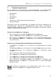
IQ8Wireless Funkkoppler für Wandmontage Der Montageort des Funkkopplers sollte so gewählt werden, dass die kürzeste Übertragungsstrecke (Funkweg) zu den Funksockeln realisiert werden kann und möglichst keine störende elektromagnetische Beeinflussung zu erwarten ist.
IQ8Wireless Funkkoppler für Wandmontage Abschwächung des Funksignals max. 300m* 0% bis -10% Holz, Gips, Leichtbauwände -5% bis -35% Backstein (oder Trennwände mit Isolierfüllung) -30% bis -90% armierte Betonwand -90% bis -100% Metall, Metallgitter Alukaschierung Abb. 1: Abschwächung des Funksignals bei mechanischen Hindernissen (in Prozent) * Maximale Reichweite bei Sichtkontakt zwischen Funksockel und Funkkoppler sowie optimalen technischen Rahmenbedingungen. FB 798941 / 10.
IQ8Wireless Funkkoppler für Wandmontage 3 Montage Der Funkkoppler ist mit geeignetem Befestigungsmaterial (wie z.B. Dübel + Schrauben) lagerichtig auf einer stabilen Wandfläche ohne mechanische Verspannung des Gehäuses zu montieren.Der Montageort sollte so gewählt sein, dass eine gute Funkverbindung (Feldstärke) zwischen dem Funkkoppler und den zugehörigen Funksockeln gewährleistet werden kann. Die Qualität der Funkverbindung kann mit der Programmiersoftware tools 8000 ab V1.09 überprüft werden.
IQ8Wireless Funkkoppler für Wandmontage LED 1 Betrieb (grün) leuchtet im Normalbetrieb LED 2 Sammelfeuer (rot) leuchtet, wenn die Feuermeldung eines zugeordneten Funkteilnehmers erkannt wurde. Das Relais >Sammelfeuer< wird angesteuert. LED 3 Sammelstörung (gelb), Anzeige nicht speichernd leuchtet, wenn eine Störungsmeldung des Funkkopplers oder eines zugeordneten Funkteilnehmers erkannt wurde.
IQ8Wireless Funkkoppler für Wandmontage 4 Installation 4.1 Anschluss der Spannungsversorgung Die Spannungsversorgung kann von der Brandmelderzentrale oder einem externen Netzteil erfolgen. Zur Spannungsversorgung des Funkkopplers ist eine eigene, separat abgesicherte, Versorgungsleitung zu installieren. Das Anschlusskabel muss den Richtlinien zum Funktionserhalt in Brandmeldesystemen entsprechen.
IQ8Wireless Funkkoppler für Wandmontage 4.2 Betrieb als Teilnehmer Analog-Ringleitung Der Funkkoppler wird direkt an die Analog-Ringleitung des Brandmeldesystems IQ8Control angeschlossen. Alle Meldungen des Funkkopplers werden über die Analog-Ringleitung zur Brandmelderzentrale IQ8Control übertragen. Die zugeordneten Funkteilnehmer können in einzelne Meldergruppen aufgeteilt werden. Bei einer Meldung eines Funksockels wird dann die Meldergruppe und Meldernummer des Funksockels (inkl.
IQ8Wireless Funkkoppler für Wandmontage 4.3 Betrieb an Standard Meldergruppe(n) Über die Relais kann der Funkkoppler an den Standard-Meldergruppeneingang eines Brandmeldesystems angeschlossen werden. Alle Funkteilnehmer bilden eine gemeinsame Meldergruppe an diesem Funkkoppler. Eine Aufteilung in mehrere, unterschiedliche Meldergruppen ist nicht möglich. Der Meldergruppeneingang wird mit dem Widerstand (R1) an dem invers betriebenen, im Ruhebetrieb angesteuerten, Sammelstörungsrelais angeschlossen.
IQ8Wireless Funkkoppler für Wandmontage 4.3.1 Betrieb an zwei getrennten Standard Meldergruppen Mit dieser getrennten Anschaltung zur Feuer- und Störungsmeldung kann nach einer Störungsmeldung (z.B. die Batterie eines Funksockels ist zu schwach) noch zusätzlich eine Feuermeldung übertragen werden. Die Störungsmeldung ist nicht speichernd und setzt sich nach Beseitigung der Meldungsursache automatisch zurück.
IQ8Wireless Funkkoppler für Wandmontage 4.4 Stand-alone Betrieb Im Stand-alone Betrieb kann der Funkkoppler, ohne weitere Anschaltung an eine Brandmelderzentrale, als eigenständiges Gerät betrieben werden. Zum Anschluss von lokalen Signalgebern für die Feuer- und Störungsmeldung stehen die beiden Relaisausgänge >Sammelfeuer< (Sa-Feu) und >Sammelstörung< (Sa-Stör) zur Verfügung. Über das Relais Sammelstörung kann auch eine Meldung, z.B.
IQ8Wireless Funkkoppler für Wandmontage 4.5 Relaisausgänge Der Funkkoppler verfügt über die zwei Relaisausgänge >Sammelfeuer< >Sammelstörung<. Die Schaltfunktion der beiden Relais kann nicht verändert werden. und Beim Anschluss des Funkkopplers an eine Standard-Meldergruppe werden beide Relais beschaltet und stehen somit nicht mehr für die Schaltfunktion >Sammelfeuer< bzw. >Sammelstörung< zur Verfügung. Sa-Feuer C NC NO Sa-Stör R P externe Geräte C NO NC externe Geräte Abb.
IQ8Wireless Funkkoppler für Wandmontage 4.6 R Eingänge P 1 2 Schnittstelle 3 4 5 UB Eing 6 + - + - Abb. 10: Lage der Anschlussklemmen 4.6.1 R-Eingang Eingang für den Anschluss des Funkkopplers an eine Standard-Meldergruppe. Dieser Eingang wird für die Rücksetzfunktion benötigt. Beim Anschluss des Funkkopplers an die AnalogRingleitung des Brandmeldesystems IQ8Control darf der Eingang nicht beschaltet werden. 4.6.2 P-Klemme Freie Stützpunktklemme 4.6.
IQ8Wireless Funkkoppler für Wandmontage 5 Inbetriebnahme Zur Inbetriebnahme des Funkkopplers ist die Programmiersoftware tools 8000 ab Version V1.09 sowie das Zentraleninterface (Art.-Nr. 789862) und ein Service-PC erforderlich. Die Inbetriebnahme unterscheidet sich abhängig davon, ob der Funkkoppler als Teilnehmer der Analog-Ringleitung installiert ist oder an einen Standard-Meldergruppeneingang angeschlossen wurde.
IQ8Wireless Funkkoppler für Wandmontage 5.1 Analog-Ringleitung 1. Schließen Sie den Funkkoppler - wie im Abschnitt „Installation“ beschrieben - an die Analog-Ringleitung des Brandmeldesystems IQ8Control und die externe Spannungsversorgung an. 2. Schalten Sie die Brandmelderzentrale bzw. die Analog-Ringleitung ein, an der der Funkkoppler angeschaltet ist.
IQ8Wireless Funkkoppler für Wandmontage 5.2 Standard-Meldergruppeneingang 1. Schließen Sie die externe Spannungsversorgung an den Funkkoppler, wie im Kapitel „Installation“ beschrieben, an. 2. Schließen Sie den Service-PC über das Zentraleninterface (Art.-Nr. 789862) an die Anschlussklemmen für die Analog-Ringleitung des Funkkopplers an und starten Sie die Programmiersoftware tools 8000. 3. Führen Sie mit dem Service-PC und der Programmiersoftware tools 8000 eine Verdrahtungserkennung durch. 4.
IQ8Wireless Funkkoppler für Wandmontage 5.3 Wichtige Hinweise zum Umgang mit Batterien Hinweise zum Stromverbrauch und zum Umgang mit den Batterien (Art.-Nr. 805597) für den Einsatz in IQ8Wireless Funkkomponenten: • Batterien erst kurz vor der Inbetriebnahme (Zuordnung zu den Funkkopplern) in die Funkteilnehmer einsetzen! Nicht zugeordnete Funkteilnehmer haben einen ca. 4-mal höheren Stromverbrauch.
IQ8Wireless Funkkoppler für Wandmontage • Batteriepole und -kontakte der Funkteilnehmer nicht mit bloßen Fingern berühren ! Durch einen Fettfilm wird ein Übergangswiderstand zwischen den Batterien und Kontakten gebildet. Dieser Übergangswiderstand kann zu einer verfrühten bzw. falschen Anzeige zur Batterieunterspannung (Batt. < 30) an der BMZ führen. • Unsachgemäße Lagerung der Funkteilnehmer und Batterien können solche Übergangswiderstände (z.B. durch Korrosion) verursachen. Kontakte ggf.
IQ8Wireless Funkkoppler für Wandmontage 6 Technische Daten Betriebsspannungsbereich : 9 V DC bis 30 V DC Betriebsspannung : 12 V DC oder 24 V DC Kontaktbelastung : max. 30 V DC / 1A Ruhestrom : ca. 17 mA @ 12 V DC Alarmstrom : ca. 18 mA @ 12 V DC Frequenzband : 433 / 868 MHz Reichweite : bis max.
Operation and Installation Instruction IQ8Wireless transponder for wall mounting (Part No. 805595) 798941 10.
IQ8Wireless transponder for wall mounting Intended purpose This product must only be used for the applications outlined in the catalogue and the technical description and in combination with external components and systems which have been approved or recommended by the manufacture. Warning In order to ensure correct and safe operation of the product, all guidelines concerning its transport, storage, installation, and mounting must be observed. This includes the necessary care in operating the product.
IQ8Wireless transponder for wall mounting Table of contents Page General.................................................................................................................................................26 System design information .................................................................................................................27 Assembly..............................................................................................................................................
IQ8Wireless transponder for wall mounting 7 General The IQ8Wireless transponder, in combination with the associated IQ8Wireless detector bases (Part No. 805593) and IQ8Wireless interfaces enables the wireless connection of IQ8Quad series fire detectors and may be used as a device on the analog loop of the IQ8Control fire alarm system or as a stand-alone wireless control device in fire alarm systems with conventional detector zones.
IQ8Wireless transponder for wall mounting 8 System design information When fire alarm systems are planned and installed in the Federal Republic of Germany, they must comply with certain standards and guidelines, including the following: • DIN VDE 0100 • DIN 14675 • DIN VDE 0833 • DIN EN54 • VdS Guidelines (VdS Schadenverhütung GmbH, Cologne) • Local building authority conditions In principle, these requirements and specifications should also be complied with in the planning of fire alarm syst
IQ8Wireless transponder for wall mounting The installation location of the IQ8Wireless transponder should be chosen so that the shortest transmission path (wireless path) to the wireless bases can be implemented and that no electro-magnetic interference is to be expected.
IQ8Wireless transponder for wall mounting Weakening of the wireless signal max. 300m* 0% to -10% Timber, plasterboard, leight-weight partition walls -5% to -35% Brick (or insulated partition walls) -30% to -90% Reinforced concrete wall -90% to -100% Metal, metal grating, aluminium lining Fig.
IQ8Wireless transponder for wall mounting 9 Assembly The IQ8Wireless transponder should be installed with suitable fixing material (such as wall plugs and screws) in the proper position on a stable wall surface with no mechanical stress of the housing. The mounting place location of the IQ8Wireless transponder should be chosen so that a good wireless link (field strength) between the transponder and the assigned IQ8Wireless detector bases is guaranteed.
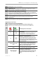
IQ8Wireless transponder for wall mounting LED 1 LED 2 LED 3 LED 4 c Operation (green) Lits in normal operation Common fire alarm (red) Lits when the fire alarm of an assigned wireless device has been detected. The relay >common fire alarm< is activated. Common trouble (yellow), display not latched Lits when a fault message from the IQ8Wireless transponder or an assigned wireless device has been detected. Activation of the >common fault< relay is interrupted and the relay contact changes position.
IQ8Wireless transponder for wall mounting 10 Installation 10.1 Connecting the power supply The power supply can come from the fire alarm control panel or from an external power unit. To supply power to the IQ8Wireless transponder you must install a separate, protected supply line. The connection cable must comply with the guidelines relating to the functions of fire alarm systems.
IQ8Wireless transponder for wall mounting 10.2 Operation as a device on the analog loop The IQ8Wireless transponder is connected directly to the analog loop of the IQ8Control fire alarm control system. All reports from the transponder are transmitted via the analog loop to the IQ8Control fire alarm control panel. The assigned wireless devices can be split into individual detector zones. If a report is sent from a IQ8Wireless base, the detector zone and detector number of the IQ8Wireless base (incl.
IQ8Wireless transponder for wall mounting 10.3 Operation on a conventional detector zone The IQ8Wireless transponder can be connected to the conventional detector zone input of a fire alarm system via the relays. All IQ8Wireless devices form a common detector zone on this IQ8Wireless transponder. You cannot split these into several, different detector zones.
IQ8Wireless transponder for wall mounting 10.3.1 Connection of two detector zones for individual fire and fault alarm The application provides the separate transmission of a fault alarm (e.g. battery low message) and an additional fire alarm message. The fault message is non-latching and is resetted automatically after the cause of the fault alarm is not present anymore.
IQ8Wireless transponder for wall mounting 10.4 Stand-alone operation In the stand-alone mode the transponder operates with no need of any further connections to a fire alarm system. To connect local arm devices the relay common fire (Sa-Feu) and/or common fault (Sa-Stör) may be used. A fault message may be transmitted via the common fault relay to, e.g. a supervising system or an authorized person. Reset To reset the transponder connect an external reset button (refer to c) or a relay contact.
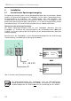
IQ8Wireless transponder for wall mounting 10.5 Relay outputs The transponder provides two relay outputs >common fire alarm< and >common fault<. The operation of the two relays cannot be changed. If the transponder is connected to a conventional detector zone, the two relays are connected and are thus no longer available for the >common fire alarm< or >common fault< switch functions. Sa-Feuer C NC NO Sa-Stör R C NO NC P external devices external devices Fig.
IQ8Wireless transponder for wall mounting 10.6 R Inputs P 1 2 Schnittstelle 3 4 5 UB Eing 6 + - + - Fig. 23: Position of the terminals 10.6.1 R - input Input for connecting the transponder to a standard detector zone. This input is required for the reset function. If the transponder is connected to the analog loop of the IQ8Control fire alarm system, the input must not be connected. 10.6.2 P - terminal Free terminal point 10.6.
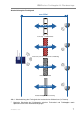
IQ8Wireless transponder for wall mounting 11 Commissioning To start the IQ8Wireless transponder you will need the tools 8000 programming software from version V1.09 or higher and the panel interface (Part No. 789862) as well as a service PC. Start-up differs depending on whether the transponder is connected as a device on the analog loop or to a standard detector zone input. Example: IQ8Wireless transponder 1 recognises all the wireless bases with adequate field strength (coloured dark here).
IQ8Wireless transponder for wall mounting 11.1 Analog loop 1. Connect the IQ8Wireless transponder to the analog loop of the IQ8Control fire alarm system and the external power supply as described in "Installation". 2. Switch on the fire alarm control panel or the analog loop to which the IQ8Wireless transponder is connected. If several IQ8Wireless transponders are connected, start these up one after the other to prevent multiple assignment of one wireless device. 3.
IQ8Wireless transponder for wall mounting 11.2 Conventional detector zone input 1. Connect the external power supply to the IQ8Wireless transponder as described in "Installation". 2. Connect the service PC to the terminals for the analog loop of the IQ8Wireless transponder via the panel interface (Part No. 789862) and start the tools 8000 programming software. 3. Conduct a wiring recognition with the service PC and tools 8000. 4. Click the required IQ8Wireless transponder to open the programming dialog.
IQ8Wireless transponder for wall mounting 11.3 Important battery information Battery information relating to power consumption and batteries (Art. No. 805597) for use in IQ8Wireless RF components • Insert batteries into the RF devices shortly before initial operation (assigned to the RF transponders)! Unassigned RF devices consume approx. 4 times more power. • Bear in mind the sufficient remaining field strength! Operation with low field strength causes the power consumption to be somewhat higher.
IQ8Wireless transponder for wall mounting • Do not touch the battery poles or contacts of the RF devices with bare fingers! A layer of grease causes transfer resistance to build up between the batteries and contacts. This transfer resistance may lead to the FACP prematurely or incorrectly displaying low battery voltage (batt. < 30). • Improper storage of the RF devices and batteries may be the cause of such transfer resistance (e.g. due to corrosion).
IQ8Wireless transponder for wall mounting 12 Specifications Power supply range : 9V DC to 30 V DC Operating voltage : 12 V DC or 24 V DC Contact rating : max. 30V DC / 1 A Quiescent current : approx. 17 mA @ 12 V DC Alarm current : approx. 18 mA @ 12 V DC Frequency band : 433/868 MHz Range of transmission path : up to max.
IQ8Wireless transponder for wall mounting Notes FB 798941 / 10.
Novar GmbH a Honeywell Company Dieselstraße 2, D-41469 Neuss Internet: www.novar.de E-Mail: info@novar.