ENGLISH Installation & Operation Guide Digital Deadbolt Model DDBKP Read this manual carefully before installing and operating! Page 1
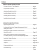
Index INSTALLATION INSTRUCTIONS Package Contents / Tools Required.......................................................... Page 1 Prepare Door and Jamb............................................................................. Page 2 Adjusting Deadbolt Latch Set.................................................................. Page 3 Installing Deadbolt Latch Set..................................................................... Page 4 Installing Exterior Assembly.......................................
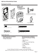
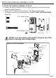
INSTALLATION INSTRUCTIONS Package Contents Entry keys (2 ea.) Deadbolt Latch Set (Adjustable) 2-3/8” (60mm) to 2-3/4” (70mm) Mounting Plate Interior Assembly Exterior Assembly 5/16” (8mm) Screws - 2 ea. 1” (25mm) Screws - 2 ea. 3/4” (19mm) Screws - 5 ea. 1-3/8” (35mm) Screws - 1 ea.
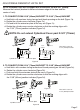
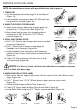
ADJUSTABLE DEADBOLT LATCH SET NOTE: Deadbolt Latch Set is shipped with the backset set at 2-3/8” (60mm) Measure the backset (backset is distance between edge of the door and the center of Lock). 1. TO CONVERT FROM 2-3/8” (60mm) BACKSET TO 2-3/4” (70mm) BACKSET a. Hold latch with numbers facing forward and thumb pressing on the bolt (Figure 1a). b. Rotate the cylinder cover clockwise (Figure 1b). c. Pull and twist the extension plate all the way out (Figure 1c). d.
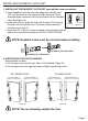
PREPARE DOOR AND JAMB NOTE: For installation on doors with pre-drilled holes skip to page 4. 1. TEMPLATE a. Cut out template printed on page 15 of this Manual (Figure 1a). b. Fold template and place on door 36” (925mm) from the ground as marked (Figure 1b). 2. MARK THE DOOR FOR DRILLING b. Mark center hole on door edge through guide on template for 1” (25mm) latch bolt (Figure 2a). a. Mark center hole on door face through guide on template for 2-3/8” (60mm) or 2-3/4” (70mm) backset (Figure 2b). 3.
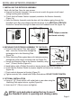
INSTALLING DEADBOLT LATCH SET 1. INSTALLING THE DEADBOLT LATCH SET (need phillips head screwdriver) a. Insert Deadbolt Latch Set into door edge hole with the word “UP” and the arrow on the extension plate facing UP. Cross shaped spindle connector will be at the bottom of the Deadbolt Latch Set (Figure 1a). b. Make sure the face plate sits flush with the door. Do not force the latch into the mortise flush. Chisel out excess material if Figure 1a necessary for a flush fit. c.
INSTALLING EXTERIOR ASSEMBLY 1. INSTALLING THE EXTERIOR ASSEMBLY Work with the Door Open for easy access. a. Unpack the Exterior Assembly. Use care to not scratch the green circuit board during handling and installation. b. Check that the Rubber Gasket is properly seated on the Exterior Assembly (Figure 1a). c. Insert the Exterior Assembly onto the door with the tailpiece going through the Deadbolt Latch Set cross shaped spindle connector in the VERTICAL POSITION.
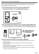
INSTALLING INTERIOR ASSEMBLY Unpack the Interior Assembly. Remove the battery cover by sliding the cover upward. Locate the screws holding the Mounting Plate to the Interior Assembly. Remove the screws to release the Mounting Plate from the Interior Assembly. 1. SET THE ENTRY SWITCH FOR LEFT OR RIGHT HANDED DOOR a. Gently move the switch to “L” for Left Handed Door (Figure 1a). b. Gently move the Switch to “R” for Right Handed Door (Figure 1b). Entry Switch (Left or Right) Figure 1a-1b 2.
INSTALLING INTERIOR ASSEMBLY (CONT.) 4. ATTACH THE INTERIOR ASSEMBLY TO DOOR a. Position the Interior Assembly over the tailpiece and push the Interior Assembly against the door (Figure 4a). b. Using two 5/16” (8mm) screws and one 1-3/8” (35mm) screw, attach the Interior Assembly to the Mounting Plate. DO NOT OVER TIGHTEN SCREWS (Figure 4b). 5/16” (8mm) screws 1-3/8” (35mm) screw Figure 4a-4b NOTE: Lock and unlock using Interior Knob to see if the latch is opening and closing easily.
INSTALLING INTERIOR ASSEMBLY (CONT.) 5. Installing Batteries a. Insert 4 AA high quality Alkaline batteries into the Battery Compartment in the direction noted +/- on the Compartment. The Lock will beep 2 times, the key pad will illuminate blue, and the Honeywell button will flash green twice to signify that it has received power (Figure 5a). NOTE: Do not touch the keypad until the blue light turns off. Do not use rechargeable batteries or non-alkaline batteries. b.
OPERATION INSTRUCTIONS Exterior Assembly Overview Indicator light Green • Indicates Successful Programming Step • Indicates Unlocking is Successful Red • Indicates Failed Programming Step • Indicates Locking is Successful Lock button Lock - Used to lock door Clear - Used to clear wrong keypad entries Unlock button Unlock - Used to unlock door Programming - Used in programming steps Batteries (not included) Electronic lock requires (4) High Quality AA Alkaline batteries.
Locking and Unlocking TO UNLOCK THE LOCK Using Keypad: Enter a valid User Code (default code is 1234) and press and hear 1 beep and lights green. TO LOCK THE LOCK Using Keypad: Press and then hear 2 beeps and lights red. Changing Programming Code CHANGE CURRENT OR PRESET PROGRAMING CODE PC PC Factory default Programming Code = 123456, this is the master password for your lock. All programming functions require this code.
Deleting User Codes DELETE ONE EXISTING OR PRESET USER CODE UC ID The unit comes with a factory User ID = 01 for User Code = 1234. UC UC the lock must have more than 1 User Code IMPORTANT: To delete 1 User Code , in its database.
Secure Lock out Period Warning sounds and LED flashes red after 4 incorrect code attempts: Keypad shuts down for 30 seconds. Restore Factory Settings To reset the lock to the original factory settings including the Programming Code PC UC and all User Codes remove one battery for 10 seconds. Reinsert the battery and wait for a long and short beep. Press 3 times within 3 seconds. The lock will beep and the light indicator will turn green.
INSTALLATION TROUBLE SHOOTING Issue Solution Latch Working BackwardsLock unlocks when lock button is pushed or locks when unlock button or code is pushed. Direction switch is set to incorrect setting. Remove the Interior Assembly and move the switch to the opposite direction. • Check that your switch is set in the correct position Left or Right Handed door. If Correct • Rotate Turn knob and reinstall Interior Assembly. Retest again while holding Interior Assembly in place.
CONSUMER ASSISTANCE EMAIL: LHLPCustomerService@LHLPinc.com WEBSITE:www.honeywellsafes.com ADDRESS: Consumer Assistance Dept. LH Licensed Products, Inc.860 East Sandhill Avenue Carson, CA 90746 USA TELEPHONE: US/Canada 1-877-354-5457 (Toll Free) Mexico 01-800-288-2872 After English voice recording stops you must then enter 800860-1677 to complete your call.
Page 15 MARK FOR 1-3/8” (35mm) DOOR THEN DRILL 1” (25mm) HOLE IN CENTER DOOR OF EDGE 2” (50mm) IN DEPTH MARK FOR 1-3/4” (45mm) DOOR IMPORTANT! PLACE TEMPLATE ON HIGH EDGE OF DOOR BEVEL 2-3/4” (70mm) BACKSET 2-3/8” (60mm) BACKSET DRILL 2-1/8” (54mm) HOLE
BACK OF TEMPLATE Page 16
Programming Record My Codes: Programming Code Date Created (6 digits) / / User Code 01 (4-8 digits) / / User Code 02 (4-8 digits) / / User Code 03 (4-8 digits) / / User Code 04 (4-8 digits) / / User Code 05 (4-8 digits) / / User Code 06 (4-8 digits) / / User Code 07 (4-8 digits) / / User Code 08 (4-8 digits) / / User Code 09 (4
Lifetime Mechanical and Finish Warranty / 1 Year Limited Electronics Warranty This product comes with a lifetime mechanical and finish warranty and a one year limited electronics warranty to the original residential consumer against defects in material and workmanship under normal use as long as the original residential purchaser occupies the residential premises upon which the product was originally installed.