
Datasheet


5
sensing.honeywell.com
Push-Pull and E-Stop Switches
Characteristics Description
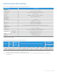
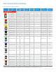
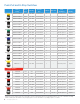
Electrical
Nominal voltage 12 dc, 24 dc, 48 dc, or C300*
Current, max. 20 A @ 12 Vdc, 10 A @ 24 Vdc, 4 A @ 48 Vdc
Current, min. 0.1 A, resistive
Dielectric 500 Vdc or 707 Vdc for 1 minute, 5 mA max.
Voltage drop 1 Vdc at rated dc loads, max.
Mechanical
Operating force 27 N ±14 N
Life 25,000 cycles at rated load
Handle shock 1 m [39.37 in] drop to hard surface
Vibration 10 g max., 18 Hz to 1000 Hz
Connector Screw terminals (combo-head), wire harness with 4-pin Deutsch connector
Environmental
Humidity 95 % non-condensing
UV color fade DE 3 max. at 15,000 hours UVB, ASTM G 154-06
Temperature
Operating -40 °C to 40 °C [-40 °F to 104 °F]
Storage -40 °C to 80 °C [-40 °F to 176 °F]
Sealing 50058830-05 is IP67 rated
Approvals UL, CE (select listings)
Table 1. Electrical, Mechanical, and Environmental Specifications
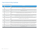
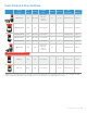
Table 2. Electrical Ratings based on Utilization Categories
Designation
1
Utilization
Category
Conventional
Enclosed
Thermal
Current I
the
(A)
Rated Operational Current I
e
(A) at Rated Operational Voltage
VA Rating
VA
ac — 120 V 240 V 380 V 480 V 500 V 600 V Make Break
C300 AC-15
2,5 1,5 0,75 — — — — 1800 180
Note 1: The letter stands for the conventional enclosed thermal current and identifies (ac or dc): for example B means 5 A ac. The rated
insulation voltage U
i
is at least equal to the number after the letter
Note 2: The rated operational current I
e
(A), the rated operational voltage U
e
(V) and the break apparent power B (VA) are correlated by the
formula B=Ue . le
*For details, please refer Table 2