
Use and Care Manual


4
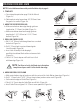
NOTE: Tailpiece must be
positioned vertically
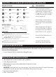
INSTALLING EXTERIOR ASSEMBLY
7. SECURING THE EXTERIOR ASSEMBLY TO THE DOOR
route the Control Wire through the rectangular
b. Place Mounting Plate against door with tailpiece passing
c. Secure the Mounting Plate to the Exterior Assembly using
d. Hand tighten with a Phillips Screwdriver leaving loosely
DO NOT OVER TIGHTEN
8. OPTIONAL INSTALLATION
a. Using a 1/16” (2mm) drill bit, drill a pilot hole in your door using the Mounting Plate
upper hole as a guide (Figure 8a).
b. Insert one 3/4” (19mm) screw and tighten.
Mounting Plate
3/4” (19mm) screw
(Optional Installation)
7/8” (22mm) screws
Control Wire
Figure 8a
Figure 7a-7f
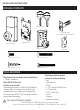
6. INSTALLING THE EXTERIOR ASSEMBLY
remove the battery cover by sliding the cover upward. Locate the screws holding the Mounting Plate to the
a. Unpack the Exterior Assembly. Use care to not scratch the green circuit board during handling and
installation.
c. Insert the Exterior Assembly onto the door with the tailpiece going through the Latch spindle in the
VERTICAL POSITION.
Rubber
Gasket
Figure 6a-b
NOTE: Lock and unlock using the key to see if
the Latch is opening and closing easily.
Control
Wire
Tailpiece
(Vertical)
Latch
Hole
Figure 6c