ENGLISH User Guide Square Faceplate Digital Bluetooth Door Knob Model 8832001S 8832101S 8832301S 8832401S Package Includes: 1 - Exterior Faceplate 1 - Interior Faceplate 1 - User Guide 2 - Keys Exterior Faceplate 1 3/8” Screws Interior Faceplate 1 - Strike Plate 1 - Mounting Plate 1 - Latch 1 - 1 3/8” Screws User Guide 1” Screws Keys 5/16” Screws Strike plate 2 - 5/16” Screws 2 - 1 “ Screws 5 - 3/4” Screws Mounting Plate Latch 3/4” Screws Please carefully check the above list to confirm al
INDEX I. INSTALLATION INSTRUCTIONS Product Overview / Tools Required.......................................................................................................... Page 1 Prepare Door and Jamb............................................................................................................................... Page 2 Adjusting And Installing Latch..................................................................................................................
INSTALLATION INSTRUCTIONS PACKAGE CONTENTS Entry keys (2 ea.) Latch (Adjustable) 2-3/8” (60mm) to 2-3/4” (70mm) Interior Assembly Mounting Plate Exterior Assembly 5/16” (8mm) Screws - 2 ea. 7/8” (22mm) Screws - 2 ea. 3/4” (19mm) Screws - 5 ea. 1” (25mm) Screw - 1 ea.
PREPARE DOOR AND JAMB NOTE: For installation on doors with pre-drilled holes skip to page 4. 1. TEMPLATE a. Cut out template printed on page 20 of this Manual (Figure 1a). b. Fold template and place on door 36” (915mm) from the ground as marked (Figure 1b). 2. MARK THE DOOR FOR DRILLING b. Mark center hole on door edge through guide on template for 1” (25mm) latch bolt (Figure 2a). a. Mark center hole on door face through guide on template for 2-3/8” (60mm) or 2-3/4” (70mm) backset (Figure 2b). 3.
ADJUSTING AND INSTALLING LATCH NOTE: Latch is shipped with the backset set at 2-3/8” (60mm) Measure the backset (backset is distance between edge of the door and the center of Lock). TO CONVERT FROM 2-3/8” (60mm) BACKSET TO 2-3/4” (70mm) BACKSET 2-3/8” (60mm) PULL TO CONVERT FROM 2-3/4” (70mm) BACKSET TO 2-3/8” (60mm) BACKSET 2-3/4” (70mm) PUSH NOTE: Curved part of Latch always faces curved portion of Strike Plate 5. INSTALLING THE LATCH (need phillips head screwdriver) a.
INSTALLING EXTERIOR ASSEMBLY 6. INSTALLING THE EXTERIOR ASSEMBLY Work with the Door Open for easy access. To access the mounting plate, unpack the Interior Assembly and remove the battery cover by sliding the cover upward. Locate the screws holding the Mounting Plate to the Interior Assembly. Remove the screws to release the Mounting Plate from the Interior Assembly. a. Unpack the Exterior Assembly. Use care to not scratch the green circuit board during handling and installation. b.
INSTALLING INTERIOR ASSEMBLY 9. ATTACH THE CONTROL WIRE TO THE INTERIOR ASSEMBLY a. Use care to attach the Control Wire male plug to the Interior Assembly female socket connector (Figure 9a). b. Do not force the Control Wire male plug into the Interior Assembly female socket connector (Figure 9b). c. The Control Wire male plug has two alignment tabs on the smooth side of the plug which is the top of the plug (Figure 9c). d.
INSTALLING INTERIOR ASSEMBLY 11. Installing Batteries a. Insert 4 AA high quality Alkaline batteries into the Battery Compartment in the direction noted +/- on the Compartment. The Lock will beep 2 times, the keypad will illuminate blue, and the Honeywell button will flash green twice to signify that it has received power (Figure 11a). NOTE: Do not touch the Keypad until the blue light turns off. Do not use rechargeable batteries or non-alkaline batteries. b.
HONEYWELL LOCK MOBILE APPLICATION INSTALLATION & USE VERY IMPORTANT PRIMARY APP ICONS Unlock Messages Users User Menu Dropdown Save Records Settings eKey Edit Passcode Locks Safes Add Device Once the door is unlocked with the App, you will have to manually lock it.
CONNECT TO BLUETOOTH LOCK IMPORTANT: Your Bluetooth must be enabled and you must be within range of the lock. 1. Press any key on Lock to activate the Lock. (Digital keys are lit when activated). 2. Click the “+” icon on the start screen. 3. Select which type of lock you would like to add 4. Click on available lock 5. Follow prompts to name the device After you have connected the lock to the Bluetooth App, the Admin. Digital Passcode must be reprogrammed by going to the “Lock Setting” page.
USING APP TO LOCK AND UNLOCK UNLOCK DOOR WITH THE APP 1. Open App, choose Lock and Touch App to Unlock 2. Open App & Touch 2 Keys to Unlock LOCK DOOR WITH THE APP 1. Open the App 2. Click on the connected safe you wish to lock 3. Press and hold the lock button until the safe has locked. AUTO LOCK If enabled in “Lock Settings”, it will automatically lock after 20 to 900 seconds. USING KEYPAD TO LOCK AND UNLOCK UNLOCK DOOR WITH KEYPAD 1. Press any key on Lock to activate the Lock.
SYSTEM SETTINGS 1. Go to the Main menu by pressing the * icon at the top left corner of the screen. 2. Select “System Settings” 3. Select below settings as desired. PATTERN PASSWORD Create a pattern to unlock the App.
ACCOUNT MANAGEMENT 1. Go to the Main menu by pressing the * icon at the top left corner of the screen. 2. Select “Account Management” 3. Select below settings as desired. PROFILE PICTURE 1. Click on the picture at the top of the page 2. Change the picture associated with the account by clicking the icon NICKNAME 1. Click on “Nickname”. 2. Enter a nickname for the account. EMAIL/MOBILE NUMBER 1. Click on “Email” 2. Enter an email address to the account. 3.
CREATE & SEND PASSCODES BY EMAIL OR TEXT MESSAGE Passcodes can be sent via email or text to any SMS enabled mobile device. SENDING PASSCODES 1. Select the lock you want to send a Passcode for 2. Select the in the bottom menu Permanent Passcodes – a. Select “Permanent” from the top tabs Timed Passcodes – a. Select “Timed” from the top tabs b. Input the time frame Cyclic (Recurring) Passcodes a. Select “Cyclic” from the top tabs b. Input the time frame One-Time Passcodes a.
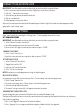
MANAGE USERS Ensure that WiFi is connected and working in order to manage Users associated with a connected lock FREEZE A USERS’ EKEY 1. Select the lock with the eKey you want to Freeze 2. Select the in the bottom menu 3. Select the User you would like to Freeze 4. Select “Freeze” 5. Confirm that you would like to Freeze the User CHANGE A U TO AU 1. Only A can authorize other Users. An AU can send eKeys and Passcodes to other Users. 2. Select the lock with the eKey you want to authorize 3.
MANAGE USERS CLEAR USER EKEYS 1. Select the lock with the eKeys you want to clear 2. Select the in the bottom menu 3. Select the top right icon 4. Select “Clear” 5. Input your account password 6. Confirm the action RESET USER EKEYS When you reset eKeys, all eKeys will be removed from the lock. 1. Select the lock with the eKeys you want to reset 2. Select the in the bottom menu 3. Select the top right icon 4. Select “Reset” 5. Input your account password 6. Confirm the action DELETE A USERS’ EKEY 1.
MANAGE USERS RESET PASSCODES When you reset eKeys, all eKeys will be removed from the lock. 1. Select the lock the Passcode is associated with 2. Select the in the bottom menu 3. Select “Passcode” from the top tab 4. Select the Dropdown icon 5. Choose “Reset Passcode” from the top selections 6. Input your account password 7.
KEY PAD PROGRAMMING - OPTIONAL Green • Indicates successful programming step EXTERIOR ASSEMBLY OVERVIEW • Indicates unlocking is successful Indicator light Red • Indicates failed programming step • Indicates locking is successful Lock button Lock - Use to lock door Unlock button Unlock - Used to unlock door Programming - Used in programming steps Batteries (not included) The electronic lock requires four (4) High Quality AA Alkaline batteries.
PROGRAMMING PHYSICAL KEYPAD 1. TURN ON/OFF AUTO LOCK FUNCTION The Physical Keypad is used to lock and unlock the door, and program functions a. Input the AP b. - Green light and beep c. 5 d. e. Input time (20 - 900 seconds, and 00 to turn off) f. - Green light and beep 2. SOUND OFF a. Input the AP b. The time between inputs can be no longer than 3 seconds. After which the programming process will be terminated. - Green light and beep c.
PROGRAMMING PHYSICAL KEYPAD 5. ADD ADMINISTRATOR To add the administrator you must use the App. Press any button on the keypad to wake up lock in order to connect. 6. CUSTOMIZE PASSCODES RECEIVED FROM THE APP a. Input the AP b. VERY IMPORTANT In order to change a Passcode, the Passcode must have been sent from the App, and used by the Receiver. - Green light and beep c. 1 d. e. Input RP f. g. NP h. i. Repeat NP j. - Green light and beep 7.
TROUBLESHOOTING Issue Lock will not function electronically. Lock gives error signal when opening or locking and Latch will not extend or retract completely when closed. The Latch is sticking. The Keypad is not working. The App is unable to connect to a lock. eKeys will not send after. Solution • Check that all batteries are fresh high quality Alkaline Batteries. • Check for proper polarity (+ -) of all batteries. • Check that the Control Wire is attached to the Interior Assembly.
20 MARK FOR 1-3/8” (35mm) DOOR THEN DRILL 1” (25mm) HOLE IN CENTER DOOR OF EDGE 2” (50mm) IN DEPTH MARK FOR 1-3/4” (45mm) DOOR IMPORTANT! PLACE TEMPLATE ON HIGH EDGE OF DOOR BEVEL 2-3/4” (70MM) BACKSET 2-3/8” (60MM) BACKSET PLACE TOP 36” (915mm) ABOVE FLOOR DRILL 2-1/8” (54mm) HOLE
BACK OF TEMPLATE 21
CONSUMER ASSISTANCE EMAIL: LHLPCustomerService@LHLPinc.com WEBSITE: www.honeywellsafes.com ADDRESS: Consumer Assistance Dept. LH Licensed Products, Inc., 860 East Sandhill Avenue Carson, CA 90746 USA TELEPHONE: US/Canada 1-800-860-1677 Ext. 1801 (Toll Free) Mexico 01-800-288-2872 After English voice recording stops you must then enter 800-860-1677 to complete your call.
FCC COMPLIANCE Regulatory Compliance This product complies with standards established by following regulatory bodies: - Federal Communications Commission (FCC) FCC This device complies with Part 15 of the FCC rules.
WARRANTY This product comes with a limited lifetime mechanical and finish warranty and a one year limited electronics warranty to the original residential consumer against defects in material and workmanship under normal use as long as the original residential purchaser occupies the residential premises upon which the product was originally installed.