N B KLN 90B GPS Abbreviated Operation Manual Rev.
N B KLN 90B GPS Abbreviated Operation Manual Rev. 1 ORS 20 IMPORTANT: Special installation procedures must be followed in order for the KLN 90B to be certified for IFR use. Consult the KLN 90B Flight Manual Supplement for the operating limitations of this unit. NOTE: Refer to the KLN 90B Pilot's Guide (006-08773-0000, Rev.1) for Database update information.
PREVIEW OF OPERATION . . . . . . . . . . . . . . . . . . . . . . . . . . . . . . 1 1.0 TURN ON . . . . . . . . . . . . . . . . . . . . . . . . . . . . . . . . . . . . . . . 3 2.0 BASIC OPERATION OF PANEL CONTROLS . . . . . . . . . . . 6 2.1 Page Selection . . . . . . . . . . . . . . . . . . . . . . . . . . . . . . . . . . 6 2.2 Entering Waypoint Identifiers . . . . . . . . . . . . . . . . . . . . . . . 8 2.3 The Duplicate Waypoint Page . . . . . . . . . . . . . . . . . . . . . . 9 3.
12.3 Adding A Waypoint To A Flight Plan . . . . . . . . . . . . . . . . 41 12.4 Deleting A Waypoint From A Flight Plan . . . . . . . . . . . . 41 12.5 Deleting Flight Plans . . . . . . . . . . . . . . . . . . . . . . . . . . . . 42 12.6 Storing FPL 0 As A Numbered Flight Plan . . . . . . . . . . . 42 13.0 OPERATING FROM THE ACTIVE FLIGHT PLAN . . . . . . 43 13.1 General Procedures . . . . . . . . . . . . . . . . . . . . . . . . . . . . 43 13.2 Turn Anticipation And Waypoint Alerting . . . . . . . . . . . .
PREVIEW OF OPERATION To give you an idea of how easy the KLN 90B is to operate, the following operational preview is presented. This operational preview assumes the KLN 90B has been properly installed, the unit was previously operational in the same general geographical location, and that no peripheral equipment interfaced with the KLN 90B (such as external HSIs, CDIs, autopilots, RMIs, fuel flow systems, moving map displays, etc.) is to be used at this time.
test page has been approved. Press the GPS CRS button to put the unit into the LEG mode. After the GPS CRS button indicates LEG, then the KLN 90B will continue the start-up process.) 3. A database page is now displayed showing the date the database expires or the date it expired. Press E to acknowledge the information displayed on this page. 4. A page displaying the letters PRESENT POS at the top will now be on the left side of the screen.
IMPORTANT: This abbreviated operation manual does not include any information on how to use the KLN 90B for flying approaches or SID/STAR procedures. Refer to the KLN 90B Pilot’s Guide and the aircraft flight manual supplement for instructions on these procedures. 1.0 TURN ON • Push the Power/Brightness knob located in the upper right corner of unit to the “in” position. The unit is turned off by pulling this knob to the “out” position.
The KLN 90B stores the correct time, date and last location of the aircraft in memory. If any of these parameters are not correct then the GPS receiver in the KLN 90B will automatically enter a mode in which it can determine this information. This usually will take less than 12 minutes, so the KLN 90B should be able to determine its position by the time you have taxied to the runway.
updated on the Self Test page when power is first applied to the KLN 90B and on the Altitude page each time a new baro correction is made to the aircraft’s altimeter. The altimeter baro setting may be changed at a later time from inches to millibars (or vice versa) on the SET 7 page. The altimeter baro set field will not be a cursor field if the KLN 90B is interfaced to certain air data/altimeter systems which update the baro set field when the aircraft’s altimeter baro setting is updated.
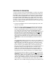
2.0 BASIC OPERATION OF PANEL CONTROLS Top Left Segment "Left Page" Lower Left Segment Top Right Segment "Right Page" Lower Middle Segment Lower Right Segment 2.1 Page Selection The screen is normally divided into five segments defined by vertical and horizontal lines on the screen. The large top left segment is called the left page and the large top right segment is called the right page.
screen by first pressing the appropriate C button (left C for left page and right C for right page) to turn the cursor function on and bring the cursor on the screen. The appropriate concentric knobs are then used to enter the data. When a cursor is on the screen, the page name normally shown in the lower left and right segments is replaced with a CRSR annunciation in inverse video.
The eight page types for the left side are the following: Page Annunciation Knob Annunciation Page Name Page Numbers TRI MOD FPL NAV CAL STA SET OTH TRIP MODE FPL NAV CALC STAT SETUP OTHER Trip Planning Mode Flight Plan Navigation Calculator Status Setup Other 0-6 1-2 0 - 25 1-5 1-7 1-4 0-9 0-4* * up to 10 with fuel management system and air data interfaces The ten page types for the right side are the following: Page Annunciation Knob Annunciation Page Name CTR REF ACT D/T NAV APT VOR NDB INT SUP CTR
NOTE: If you are entering an airport identifier that is all letters (no numbers), then it will begin with a “K” prefix in the Contiguous U.S., a “P” in Alaska, or a “C” in Canada. If there are numbers in the identifier, then a prefix is not used. For other areas of the world the airport identifier stored in the KLN 90B database is identical to how it is charted. Like all rules there are also exceptions to the guidelines given above.
waypoints in the database having the identifier. Below the identifier is a list of the waypoint types (APT, VOR, NDB, INT, SUP) and the associated countries which use the identifier. To see an example of a Duplicate Waypoint page perform the following steps: • Press D. • Turn the left inner knob to select the letter D as a waypoint identifier. “D” is the full identifier of several waypoints in the KLN 90B database. Press E. The Duplicate Waypoint page will be displayed on the left side .
the almanac data will become out of date only if the KLN 90B hasn’t been used for the previous six months or longer. Collecting new almanac data takes place automatically if the data is more than six months old. If the almanac data is out of date and needs to be collected, the KLN 90B will take a few minutes to acquire your present position (usually about six (6) minutes, but not more than 12 minutes). The Self Test and Database pages should be approved. 2.
• Press E to view the waypoint page on the right side. • Press E again to confirm the waypoint page. NOTE: As an alternative, you can also enter the approximate latitude and longitude of your present position directly on the SET 1 page instead of entering a waypoint identifier. • Use the left outer knob to position the cursor over CONFIRM?, if it is not there already. • Press E. NOTE: The groundspeed (KT) and heading ( °) fields are not used for actual initialization in an aircraft.
If this condition isn’t occurring, then: 3. If there is any waypoint page (APT 1-8 page, VOR page, NDB page, INT page, SUP page, or ACT page) in view on the right side when D is pressed, then the Direct To page will contain the identifier for the waypoint page being viewed on the right side. If neither of the conditions above are occurring, then: 4. When D is pressed, the waypoint identifier for the current active waypoint will be displayed. 5.
4.2 Direct To - Procedure B • Select the desired waypoint type (APT, VOR, NDB, INT, or SUP) on the right page. • Select the desired waypoint identifier using the following method: a. Press the right C. The cursor will be over the first character in the waypoint identifier. b. Rotate the right inner knob to select the first character of the desired identifier. c.
• Press D. The Direct To page is displayed on the left side and it contains the desired waypoint identifier. • Press E to approve the waypoint page displayed on the right side. The right side will display the NAV 1 page, and the left side will return to the page which was displayed prior to pressing D (unless the NAV 1 page was on the left side in which case the pages will revert to the state they were in prior to the direct to operation). The selected waypoint is now the active Direct To waypoint. 4.
5.0 THE NAVIGATION PAGES As you would expect, the NAV (navigation) pages contain information relating specifically to the KLN 90B’s navigation capabilities. The KLN 90B has five NAV pages. Unlike any other pages, these pages may be selected and viewed on both the left and right sides of the screen. The procedure for selecting specific pages, including the NAV pages, was described previously under “BASIC OPERATION OF PANEL CONTROLS”. NAV pages 1,2,3, and 5 are briefly described here.
contains exactly the same information as the standard NAV 1 page but spreads the data out across the entire screen making it even easier to view. 5.3 The Navigation 2 Page (NAV 2) The NAV 2 page displays the aircraft’s present position in two formats. The first format is in terms of the distance and radial from a nearby VOR. (Although terminal VOR’s are in the database, they are not used on this page since many aeronautical charts do not display a compass rose around them for orientation purposes).
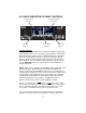
90B is interfaced with a source of heading in a suitable format then a heading up presentation may also be selected. When the North up display is selected, viewing the NAV 5 page is like looking at a navigation chart with North at the top. When the desired track up display is selected, viewing the NAV 5 page is like looking at a chart that is turned so that your course line is always pointing up.
In both the North up format and the desired track up format, the aircraft’s position is depicted by a diamond. In the actual track up format and the heading up format, the aircraft’s position is depicted by an aircraft symbol. The range scale is displayed in the lower right corner of the NAV 5 page. The range scale indicates the distance from the aircraft’s position (the diamond or aircraft symbol) to the top of the screen.
The map scale is also changed by using the left cursor button. To change the map scale, press the left C to place the cursor over the map scale factor at the bottom left corner of the map display. Turn the left inner knob to select a map scale. The map scale choices are the same as for the NAV 5 page except there is an additional choice, AUTO, that is located between the 1 nm scale factor and the 1000 nm scale factor.
tation choices are the same as for the NAV 5 page: North up, desired track up, actual track up, or heading up (if a proper source of heading is provided to the KLN 90B). Remember that for actual track up, graphics are displayed only when the aircraft is moving at a groundspeed greater than 2 knots. When the desired selections have been made, press the right C to remove the menu . One last feature of the Super NAV 5 page is that you can scan through the waypoints of the active flight plan.
6.0 MESSAGE PAGE Whenever the KLN 90B determines that there is a situation that requires the pilot’s attention, the message prompt (MSG) begins flashing in inverse video at the bottom of the display just to the right of the mode of operation. A remote message annunciator may also be installed in the aircraft instrument panel. The message should be viewed at the pilot’s earliest opportunity because the unit may be alerting the pilot of some condition of immediate concern. To view the message, press M.
use airspace. If the special use airspace is a Class B, Class C, CTA, or TMA, the message page will also instruct you to see the Airport 4 page (airport communications) for the primary airport so that the correct communications frequency may be determined. The SUA alert feature is three dimensional. The SUA areas are stored in the KLN 90B database with regard to altitude when the actual SUA altitude limitations are charted in terms of mean sea level (MSL).
trate the SUA area. If one of the SUA areas is penetrated, another message will state: INSIDE SPC USE AIRSPACE. The SUA alert feature may be disabled (or enabled) on the Setup 8 (SET 8) page. After displaying the SET 8 page on the left side, press the left C to turn on the left cursor function. The left inner knob is used to display AIRSPACE ALERT ENABLE or AIRSPACE ALERT DISABLE.
Method 1: a. Press the right C. The cursor will be over the first character in the waypoint identifier. b. Rotate the right inner knob to select the first character of the desired identifier. c. Turn the right outer knob one step clockwise to move the cursor to the second character and then use the right inner knob to select the second character. d. Use the right outer and inner knobs as in the previous two steps to complete the identifier. Method 2: a. Pull the right inner knob to the “out” position. b.
8.3 The Airport 2 Page (APT 2) The Airport 2 page contains the following information: • Airport identifier. An arrow precedes the identifier if it is the active waypoint. • The city where the airport is located. • The state if the airport is located in the United States, the Province if located in Canada, or the country if located outside the United States and Canada. A listing of the abbreviations used is contained in Appendix D of the KLN 90B Pilot’s Guide.
• The letters “RT” followed by a runway designation indicate that the runway normally has a right hand traffic pattern. For example, RT 25 31 designates that runways 25 and 31 have a right hand traffic pattern. • Airport identifier. An arrow precedes the identifier if it is the active waypoint.
AFIS - aerodrome flight information service CL B -Class B airspace (VFR frequency) CL C -Class C airspace (VFR frequency) TRSA -Terminal Radar Service Area (VFR frequency) CTA - control area (VFR frequency used outside USA) TMA - terminal area (VFR frequency used outside USA) APR - approach control DEP - departure control CTR - center (when center is used for approach/departure control) ARVL - arrival RDO - radio RDR - radar only frequency DIR - director (approach control/radar) AWOS - automatic weather obs
8.6 The Airport 5 Page (APT 5) The Airport 5 page is used to store and display user-entered remarks. Up to 100 airports may contain these remarks. A remark may contain up to three lines of eleven characters each. Letters, numbers, hyphens, and spaces may be used in the remark. To enter a remark: • Select the APT 5 page for the desired airport. • Press the right C. • Rotate the right outer knob until the cursor fills the entire third line of the screen.
CUSTMS-REST CUSTMS-ADCS Customs facilities are available on a restricted basis, check with the airport before planning to use Customs are available for private aircraft arriving to the U.S. from Canada or Mexico. Advance notice of arrival to customs officers is to be included in the flight plan transmitted to an FAA facility. This code is used when this is the only type customs facility available. The FAA term for the service is “ADCUS”.
8.10 The VOR Page The VOR page contains the following information: • VOR identifier. An arrow precedes the identifier if it is the active waypoint. • The letter “D” appears following the VOR identifier if the VOR has DME capability. • The name of the VOR. • The class of VOR T - terminal L - low altitude H - high altitude U - undefined • The VOR frequency (MHz). • The published magnetic variation of the VOR. • The latitude and longitude of the VOR. 8.
8.12 The Intersection Page (INT) The Intersection pages contain low altitude, high altitude, approach, and SID/STAR intersections as well as outer markers and outer compass locators. The following information is displayed for Intersection pages: • The intersection, outer marker, or outer compass locator name. • The location of the intersection, outer marker, or outer compass locator expressed in terms of a radial and distance from a nearby VOR. The KLN 90B chooses the closest VOR.
9.0 NEAREST AIRPORTS, VORS, AND NDBS 9.1 Viewing The Nearest Airports, VORs, And NDBs The KLN 90B computes the nine nearest airports, the nine nearest VORs, and the nine nearest NDBs to the aircraft’s present position. There is no “nearest” list for intersection and supplemental waypoints. To view the nearest airports: • Rotate the right outer knob to select the airport (APT) types. • Pull the right inner knob to the “out” position.
• Press E. The waypoint page for the nearest airport is now displayed on the right side. The right inner knob may now be used in the normal manner to scan the other nearest airports (knob in the “out” position) or to view all eight airport pages for a specific airport (knob in the “in” position). 9.3 Continuous Display Of Nearest Airport When the nearest airport page is initially displayed, “NR 1” is displayed in the upper right hand corner of the page to designate this airport as the nearest airport.
• Rotate the left outer knob one step clockwise to position the cursor over the runway surface criteria. • Turn the left inner knob to select either HRD SFT or to select HRD. If HRD SFT is chosen, then both hard and soft surface runways meeting the required runway length will be included in the nearest airport list. If HRD is chosen, then only hard surface runways will be included. Hard surface runways include concrete, asphalt, pavement, tarmac, bitumen, and sealed.
NOTE: If a waypoint page containing a latitude and longitude is displayed instead of the above text, the identifier entered already exists in the user database. Another identifier must be chosen. 10.1 Creating A Waypoint At The Present Position The first method of creating a user-defined waypoint is to define it at your present position (the position shown on the NAV 2 page). To create a waypoint in this manner: • Follow the steps just presented in section 10.0 to enter a waypoint identifier.
• Use the right inner and outer knobs to select the radial (from the reference waypoint). The radial may be selected to the nearest tenth of a degree. • Press E. The cursor will move to the dashes to the right of DIS. • Use the right inner and outer knobs to select the distance. The distance may be selected to the nearest tenth of a nautical mile. • Press E. The latitude and longitude is calculated and displayed. The user-defined waypoint is now created.
11.0 DELETING USER WAYPOINTS A listing of all user-defined waypoints is contained on the Other 3 page (OTH 3). The user-defined waypoints are listed by category; airports (A) are first, VORs (V) are second, NDBs (N) are third, Intersections (I) are fourth, and Supplemental waypoints (S) are last. Within each category, the waypoints are alphabetized by identifier. To the right of the identifier is the type waypoint defined (A,V,N,I, or S).
vated, it becomes FPL 0, the active flight plan. This manual will refer to FPL 0 as the “active flight plan” and FPL 1 through FPL 25 as the “numbered flight plans”. If desired, a flight plan can be created directly in the active flight plan. This avoids creating the flight plan in a numbered flight plan and then having to activate it. The disadvantage is that if a numbered flight plan is subsequently made active, the one programmed directly into FPL 0 will be lost.
page allowing creation of a user defined waypoint will appear on the right side. Refer to section 10.0, “CREATING USER WAYPOINTS”, for instruction on how to define a user created waypoint. • Press E again to approve the waypoint page being displayed. The cursor will move to the second waypoint position. NOTE: A small number of waypoints are stored in the database as “flyover” waypoints. These waypoints are associated with SID/STAR procedures.
since creating this flight plan, rotate the left outer knob all the way counterclockwise to position the cursor over USE?) • Press E to activate the flight plan in the order shown. To activate the flight plan in inverse order (first waypoint becomes last and last waypoint becomes first), rotate the left outer knob one step clockwise to position the cursor over USE? INVRT? before pressing E. • The selected flight plan is now displayed as FPL 0, the active flight plan.
• Rotate the left outer knob as necessary to position the cursor over the waypoint to be deleted. • Press @. The letters DEL (delete) will appear to the left of the identifier and a question mark will appear to the right of the identifier. If a mistake was made and you do not wish to delete this waypoint, press @. • Press E and the waypoint will be deleted from the flight plan. The other waypoints in the flight plan will be correctly repositioned. 12.
13.0 OPERATING FROM THE ACTIVE FLIGHT PLAN 13.1 General Procedures Everything described in this manual thus far is applicable to using the KLN 90B for flight plan operation.
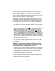
13.2 Turn Anticipation And Waypoint Alerting Prior to reaching a waypoint in the active flight plan, the KLN 90B will provide navigation along a curved path segment to ensure a smooth transition between two adjacent legs in the flight plan. That is, the CDI or HSI left/right deviation will be referenced to the dashed line in the following figure. This feature is called turn anticipation.
point page for the active waypoint will be displayed. The location of the waypoint in the flight plan (waypoint 1, waypoint 2, etc.) is annunciated with a number to the left of the identifier. In addition, an arrow to the left of the waypoint number designates the active waypoint. The letter to the far right of the identifier designates the type of waypoint: A = airport, V = VOR, N = NDB, I = intersection, S = supplemental, or T=Terminal (see KLN 90B Pilot’s Guide).
The second method takes advantage of rule number 2 described in section 4.0. To use this method: • Display the Super NAV 5 page by selecting NAV 5 on both sides of the display. • Pull out the right inner knob. A “window” will appear in the bottom right hand corner that has the current active waypoint in reverse video. • Turn the right inner knob to scan through the waypoints of the active flight plan until the desired waypoint is displayed. • Press D.
13.7 The Distance/Time 2 Page (D/T 2) When the FPL 0 page is displayed on the left side and the D/T 2 page is displayed on the right side, the distance and estimated time of arrival are displayed for each of the active flight plan waypoints. The distances are as described for the D/T 1 page. The time zone associated with the estimated time of arrival is annunciated at the top right of the D/T 2 page.
SET 4 page displays RUN WHEN POWER IS ON, then the departure time is the time when power was applied to the KLN 90B. The SET 4 page may be changed by pressing the left C while the SET 4 page is displayed on the left side and then rotating the left inner knob. Press the left C again to turn the left cursor function off. • TIME -The present time. The time may be reset on the Self Test page at system turn-on or on the SET 2 page at any time. • ETA - The estimated time of arrival at the destination waypoint.
NOTE: There may be some difference (less than 100 feet) between the indicated altitude (IND) and the aircraft’s actual altitude if the altitude input to the KLN 90B is from an altitude encoder because these encoders only provide altitude in 100 foot increments. 3. Turn the left outer knob one step clockwise to position the cursor over the ALERT: field. If OFF is displayed, turn the left inner knob to select ON.
and headphones. Or the KLN 90B may be interfaced with an external tone generator installed in the aircraft. In order to use altitude alerting, the KLN 90B must have an altitude input. If the altitude input is from an altitude encoder or from an air data computer not having a baro altitude output, then it will be necessary for you to manually input the proper altimeter setting in order to get accurate alerting.
means of interfacing the KLN 90B with the computer via an interface cable. The diskettes are not returned to ASGAA. This method of update is for use anywhere in the world that diskettes may be shipped. Directions for updating the database using a laptop computer are contained in section 2.4.1 of the KLN 90B Pilot’s Guide. In order to utilize the first method of database update, exchanging the KLN 90B cartridge, it is necessary to remove the KLN 90B from the aircraft’s instrument panel.
• Insert the old cartridge into the container. Peel off the protective backing from the adhesive on the end flap on the container. Press the flap against the adhesive to seal the container. • Please return the old cartridge promptly by mailing immediately at any mailbox. No postage is required if mailed from within the U.S. Users will be billed for cartridges not returned, and no additional cartridges will be sent until either the old cartridge or payment for the old cartridge is received. 16.
Honeywell Aerospace Business and General Aviation Honeywell International Inc. One Technology Center 23500 West 105th Street Olathe, KS 66061 Telephone: (913) 712-0400 FAX: (913) 712-1302 www.honeywell.com 006-08774-0000 Rev. 1 06/97 © 2000-2006 Honeywell International Inc.