9782 Series Two Cell Conductivity/Resistivity Analyzer/Controller Operator’s Manual 70-82-25-74 Rev 3 6/99
Copyright, Notices, and Trademarks Printed in U.S.A. – © Copyright 1999 by Honeywell Inc. Revision 3 – 6/99 While this information is presented in good faith and believed to be accurate, Honeywell disclaims the implied warranties of merchantability and fitness for a particular purpose and makes no express warranties except as may be stated in its written agreement with and for its customer. In no event is Honeywell liable to anyone for any indirect, special or consequential damages.
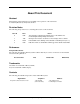
About This Document Abstract This manual contains instructions for installation and operation of the 9782 Series Conductivity/Resistivity Analyzer/Controller. Revision Notes The following list provides notes concerning all revisions of this document. Rev. ID Date Notes 0 6/98 This manual accompanies the initial release of the 9782 Series Conductivity/Resistivity Analyzer/Controller. 1 7/98 Changes were made to Section 9 to reflect changes in the software.
Contents 1. INTRODUCTION ..................................................................................................... 1-1 1.1 Description ..................................................................................................................................... 1-1 Multi-function instrument ...............................................................................................................................1-1 User interface........................................................
2. SPECIFICATIONS AND MODEL NUMBER............................................................ 2-1 2.1 Specifications ................................................................................................................................. 2-1 2.1.1 User Interface ........................................................................................................................ 2-1 Display...........................................................................................................
4. POWER WIRING ..................................................................................................... 4-1 4.1 Overview ........................................................................................................................................ 4-1 Introduction ....................................................................................................................................................4-1 What’s in this section? ...............................................
5.9 Selecting a Computed Value to Be Displayed ............................................................................. 5-21 Purpose .........................................................................................................................................................5-21 Procedure......................................................................................................................................................5-21 5.10 Summary of Menu Choices and System Defaults ..
. CALIBRATION ........................................................................................................ 8-1 8.1 Overview ........................................................................................................................................ 8-1 Introduction ....................................................................................................................................................8-1 What’s in this section? .............................................
10. MAINTENANCE................................................................................................... 10-1 10.1 Overview .................................................................................................................................... 10-1 Introduction ..................................................................................................................................................10-1 What’s in this section? ....................................................
APPENDIX B TWO-CELL APPLICATIONS................................................................B-1 Ion Exchange ................................................................................................................... ..............................B-1 Reverse Osmosis................................................................................................................ ............................B-1 Conductivity/Resistivity/TDS Difference .................................................
Tables Table 1-1 Table 1-2 Table 1-3 Table 1-4 Key Functions .......................................................................................................................... 1-6 9782 Conductivity/Resistivity Analyzer/Controller Menu Hierarchy................................... 1-11 Available Combinations of Relay Assigments ...................................................................... 1-15 Overview of Analyzer/Controller Installation Tasks.................................................
Table 10-8 Procedure for Replacing the Fuse...................................................................................... 10-16 Table 11-1 Part Numbers .......................................................................................................................
Figures Figure 1-1 Figure 1-2 Figure 1-3 Figure 1-4 Figure 1-5 9782 Front Panel..................................................................................................................... 1-5 Representative Process Value Display for a Cell in Standard Range Analyzer..................... 1-8 Representative Combined Display ......................................................................................... 1-9 Representative Computed Value Display...............................................
xiv 9782 Series Conductivity/Resistivity Analyzer/Controller - Operator’s Manual 6/99
Introduction 1. Introduction 1.1 Description Multi-function instrument The Honeywell 9782 Conductivity/Resistivity Analyzer/Controller (Figure 1-1) is a microprocessor-based instrument for analysis of conductivity, resistivity, total dissolved solids, or concentration in industrial processes. The resolution for all measurements is +/- 0.5% of reading (except for temperature; see below).
Conductivity/Resistivity Analyzer/Controller Input Input to the 9782 can be from any Honeywell conductivity cell at distances up to 1500 feet. Outputs Optional isolated 0 to 1 V, 0 to 10 V and 4 to 20 mA outputs are available. Use these analog outputs for retransmission of process variables, or for Current Adjusting Type control using an output signal that is directly proportional to the input (see 1.5.3).
Introduction 1.2 Features Automatic cell washing The standard AutoClean feature can periodically rinse cells automatically. The schedule and duration of the operation are configurable. An internal relay actuates external solenoid valves to control the flow of rinse water to the cells.
Conductivity/Resistivity Analyzer/Controller Watertight corrosion-resistant case The 9782 is enclosed in a watertight and corrosion resistant industrial case, designed for panel, pipe or wall mounting. It has an EMI/RFI shielded plastic case. Solution Temperature Compensation There are two types of 9782C Analyzer/Controller models: standard range and wide range. Both types provide temperature compensation as described below.
Introduction For semiconductor etch rinse resistivity measurements temperature compensation provides the most accurate measurements of used rinsewater containing traces of acidic etchants. Rinse quality control and water reclamation monitoring can be made with greater precision when this compensation is used.
Conductivity/Resistivity Analyzer/Controller 1.3 Operating the Analyzer/Controller 1.3.1 Keypad Use Front panel keys used for all operator tasks As shown in Figure 1-1, five keys with dedicated functions are on the front panel. In addition, three “soft keys” vary their function according to the needs of the screen on display. Use of the keys is described in Table 1-1.
Introduction Selecting a parameter for edit To select a parameter for edit: • display the screen containing the parameter • use the UP or DOWN keys to highlight the parameter name • press the ENTER key to highlight the displayed current value Editing a parameter assignment from a list of available choices To edit a parameter having a text string as an assigned value: • select the parameter and highlight its current value as described above • use the UP or DOWN keys to display the other valid cho
Conductivity/Resistivity Analyzer/Controller 1.3.2 Online Displays Introduction The online displays available when the operator presses the DISPLAY key depend on the number of cells connected to the Analyzer/Controller, and on the special features used. The instrument’s tagname (or other configurable text) is at the top of the screen for all displays except the digital clock and the AutoClean Sequence display.
Introduction Combined display If two cells are connected to the Analyzer/Controller, then a display is available that includes the measured variable for both cells (see Figure 1-3). Another combined display also includes the temperature measured by each cell. MIXED BEDS C1 0.58 C2 0.
Conductivity/Resistivity Analyzer/Controller Clock and AutoClean If the 24-hour clock is turned on, a time display will be available. If AutoClean is configured, then the AutoClean screen will be included in the display cycle (see Figure 1-5). When AutoClean is active, the screen will display the time remaining. When this screen is on display, the function keys can be used to control the AutoClean operation as described in 1.3.1.
Introduction 1.4 Menu Hierarchy Menus for every task For your convenience, menus are provided for configuration, calibration, maintenance, and I/O setup tasks. The menu hierarchy is shown in Table 1-2. Not every menu item applies to every system.
Conductivity/Resistivity Analyzer/Controller Table 1-2 9782 Conductivity/Resistivity Analyzer/Controller Menu Hierarchy Menu Item MAINTENANCE OFF-LINE FUNCTIONS do occasional system tasks Sections 9 and 10 [see functions listed below] [see below] test display 9.5.1 KEYBOARD TEST test keyboard 9.5.1 OUTPUT TESTS test relays and analog outputs 9.5.2 OUTPUT CALIBRATION calibrate outputs electrically 10.
Introduction 1.5 Planning 1.5.1 Overview Configuration system minimizes decisions The 9782C Analyzer/Controller was designed for easy configuration using menu displays and the keys on the front panel. Numeric values such as setpoints and range limits are easy to enter using the UP and DOWN keys and function keys (see 1.3). Other configuration parameter assignments are selected by scrolling through a list of available choices using the UP and DOWN keys.
Conductivity/Resistivity Analyzer/Controller Interactions affecting permitted relay assignments Table 1-3 is provided so that you can optimize your use of relays to implement your control strategy. Each row in the table represents an available combination of relay assignments for a single feature or multiple alarms. ATTENTION AutoClean and range status indication cannot be selected for use with two cells simultaneously.
Introduction Table 1-3 Available Combinations of Relay Assigments Features Used Alarms Only Relay 1 Relay 2 Relay 3 Relay 4 Alarm 1 Alarm 2 Alarm 3 Alarm 4 Alarm 1 and Diagnostic Alarm 2 Alarm 3 Alarm 4 Alarm 1 Alarm 2 and Diagnostic Alarm 3 Alarm 4 Alarm 1 Alarm 2 and Alarm 4 Alarm 3 Alarm 2 and Alarm 4 Alarm 1 and Alarm 2 Alarm 3 and Alarm 4 Alarm 1 and Alarm 2 Alarm 3 and Alarm 4 Alarm 1 or discrete control Alarm 2 or discrete control Alarm 3 or discrete control Alarm 4 or disc
Conductivity/Resistivity Analyzer/Controller 1.5.3 Deciding on a Control Strategy All 9782 models can use relays for control All 9782 models have at least two relays. (Two more relays are optional.) Unless dedicated to other functions, these relays can be used to control process variables using the three types of discrete control available. • On/Off Control using one to four cycle timers with configurable setpoint, deadband, cycle period, and “on” time.
Introduction 1.6 Overview of Installation and Setup Tasks Setup tasks described in this manual This manual contains instructions for all installation and operation tasks relating to the Analyzer/Controller. (Instructions for installing and using the cells are provided in the manuals supplied with the cells.) Table 1-3 provides an overview of the Analyzer/Controller installation tasks, as well as providing references to the relevant sections of the manual.
Conductivity/Resistivity Analyzer/Controller The manual also contains: 1-18 • information about diagnostics, status messages, and system error messages (Section 9) • instructions for returning all parameter values to the factory settings (Section 10) • instructions for calibrating the outputs and changing the fuse (Section 10) • parts list (Section 11) • supplementary information for special applications and proportional control tuning tips (appendices).
Specifications and Model Number 2. Specifications and Model Number 2.1 Specifications 2.1.1 User Interface Display LCD dot matrix display, 128 by 64 dpi. Backlit: solid state LED. Displays Cell 1 and Cell 2 values in terms of conductivity, resistivity, concentration, or TDS (temperature compensated or not compensated); Cell 1 and Cell 2 temperature; computed value (if enabled); time (if clock is enabled); time remaining in AutoClean cycle (if feature is configuration); alarm conditions, and diagnostics.
Conductivity/Resistivity Analyzer/Controller CE conformity This product is in conformance with the protection requirements of the following European Council Directives: 89/336/EEC, the Electromagnetic Compatibility Directive and 73/23/EEC, the Low Voltage Directive. Conformance of this product with any other “CE Mark” Directive(s) shall not be assumed. Year 2000 This instrument will be unaffected by the occurrence of the year 2000. 2.1.4 Electrical Power Requirements 120 +/- 10% Vac, 47-63 Hz, 15 VA.
Specifications and Model Number Wide range models Wide Display Ranges: 9782C-W0 Conductivity (microsiemens/cm) TDS Cell Constant Required (cm-1) 100-1,999 0-1,999 ppm 0.1 1000-19,990 0-19,990 ppm 1 10-199.9 0-199.9 ppt 10 10-500 — 25 20-1,000 — 50 Conductivity (millisiemens/cm) Concentration * 0-18.00% Hydrochloric Acid* 50** 0-19.99% Sulfuric Acid 50** 0-19.99% Sodium Hydroxide* 25** ro 50 0-19.
Conductivity/Resistivity Analyzer/Controller Performance under reference operating conditions Display Accuracy: Standard Ranges (Conductivity/Resistivity); ±0.5% of reading. Wide Ranges (Conductivity); ±0.5% of reading or 0.02% of span. Concentration; ±0.5% of span, ±1% conformity to conductivity vs. concentration data tables. Output accuracy: Adjustable to within 0.01 mA, repeatable to within ±0.1% of span.
Specifications and Model Number 2.1.8 Temperature Compensation Availability All models can provide high resolution (0.05º C, typical) temperature compensation by microprocessor calculation over 0 to 140º C for high purity water and concentrations as well as routine water measurements. standard range models: Temperature compensation algorithms are for NaCl, acid/cation/ammonia, or morpholine. wide range models: Temperature compensation algorithms are for NaCl, HCl, NaOH, or H2SO4.
Conductivity/Resistivity Analyzer/Controller 2.1.11 Computed Values Available selections Available Computed Values Description Equation ratio between the values measured by the cells difference between the values measured by the cells percent passage percent rejection parts per million carbon dioxide (9782C-S0 only) 2-6 Cell1 Cell 2 Cell1 − Cell 2 Cell1 x100 Cell 2 (1 − Cell1 )x 100 Cell 2 Range 0.001 to 19,990 -19,990 to 19,990 0 to 100% 0 to 100% 0 to 19.
Specifications and Model Number 2.2 Model Number Breakdown Introduction The model number breakdown is presented in the tables that follow. The basic model number consists of a key number. Appended to this key number are characters that identify the features in various categories. The meaning of the characters in each category is presented in a table identified below.
Conductivity/Resistivity Analyzer/Controller TABLE I - INPUTS pH/ORP Electrodes pH from External Pre-amp Direct Glass/Antimony pH/ORP Electrode/Internal Pre-amp Direct DURAFET pH electrode, Internal Pre-amp Direct Glass from HPW7000, Hi-pHurity Water Assembly, Internal Preamp Conductivity Cells Range Standard Wide Specific Ion Range - 0.
Specifications and Model Number Note 1: Customer must supply tagging information; Up to 3 lines allowed. (22 characters for each line) Note 2: This option for use with HPW7000 assembly only. Note 3: Standard range should be selected if measuring the following conductivity, resistivity or TDS ranges: Conductivity 0-1.999 0-19.99 0-199.9 0-1999 0-19,990 Resistivity 0-19.99M 0-1.999M 0-199.9k 0-19.99k 0-1.999k Note 4: STANDARD RANGE TDS 0-1999 ppb 0-19,990 ppb 0-199.
Conductivity/Resistivity Analyzer/Controller 2-10 9782 Series Conductivity/Resistivity Analyzer/Controller - Operator’s Manual 7/99
Unpacking, Preparation, and Mounting 3. Unpacking, Preparation, and Mounting 3.1 Overview Introduction This section contains instructions for unpacking, preparing, and mounting the Analyzer/Controller. Instructions for wiring are provided in Sections 4 and 6. Software configuration is described in Section 5. What’s in this section? The topics in this section are listed below. Topic 7/99 See Page 3.1 Overview 3-1 3.2 Unpacking and Preparing 3-2 3.
Conductivity/Resistivity Analyzer/Controller 3.2 Unpacking and Preparing Procedure Table 3-1 contains procedure for unpacking and preparing the 9782. Table 3-1 Procedure for Unpacking and Preparing the 9782 Step Action ATTENTION For prolonged storage or for shipment, the instrument should be kept in its shipping container. Do not remove shipping clamps or covers. Store in a suitable environment only (see specifications in Section 2). 1 Carefully remove the instrument from the shipping container.
Unpacking, Preparation, and Mounting Honeywell York, PA U.S.A. ATTENTION - UNIT SET FOR 240 VAC 9782C-S0-VC-E0010-00 S/N: 9751Y712345670001 USA WARRANTY ASSISTANCE - 1 - 800-423-9883 120/240 VAC 50/60 Hz 15VA Contact Rating 1 & 2: 0.6 Amps at 120/240 VAC, 0.6 Amps at 110 VDC, and 2 Amps at 30 VDC. If installed 3 & 4: 3 Amps at 120 VAC, 28 VDC. CE CASE: NEMA 4X Directions: 70-82-25-74 Figure 3-1 Sample Nameplate 3.3 Mounting Introduction The 9782 Analyzer/Controller can be panel-, wall- or pipe-mounted.
Conductivity/Resistivity Analyzer/Controller 7.00 ± .040 177.80 ± 1.02 Case Outline 6.12 ± .030 155.57 ± 0.76 Square 6.00 152.40 (2) ¼-20 Tapped Holes in rear of case for mounting bracket C L 4.81 122.17 CL 1.37 34.92 2.75 69.85 .87 Dia holes (4) 22.22 for lead wires, .50 accomodates conduit by customer 12.70 5.516 140.11 min space .687 between 17.45 horizontal cutouts Terminal Boards +.047 -0 +1.19 -0 2.41 61.21 LEGEND: inches millimeters 2.76 70.05 5.516 140.11 .125 3.
Unpacking, Preparation, and Mounting Vertical Rear Pipe Mounting inches LEGEND: millimeters 7.43 ±.070 188.72 ±1.78 3.06 77.80 7.68 ±.060 195.07 ±1.52 1.00 IPS Pipe 25.40 (by customer) Note 1: Do not exceed 80 lb-in torque when tightening fastners. Top View Panel Mounting into existing 7075, 7076, 7077, and 7078 series cutouts 7.43 ±.070 188.72 ±1.78 1.50 38.10 C L 3.00 76.20 C L 6.43 ±0.70 163.32 ±1.78 1.06 ±.025 26.92 ±0.64 Four holes in bracket or 1/4 dia.
Conductivity/Resistivity Analyzer/Controller 7.21 ± .040 183.13 ± 1.02 Case Outline 6.12 ± .030 155.57 ± 0.76 Square 6.00 152.40 (2) ¼-20 Tapped Holes in rear of case for mounting bracket C L 4.81 122.17 CL 1.37 34.92 2.75 69.85 .87 Dia holes (4) 22.22 for lead wires, .50 accomodates conduit by customer 12.70 5.516 140.11 min space .687 between 17.45 horizontal cutouts Terminal Boards +.047 -0 +1.19 -0 2.41 61.21 inches LEGEND: millimeters 2.76 70.05 5.516 140.11 .125 3.
Unpacking, Preparation, and Mounting Vertical Rear Pipe Mounting inches LEGEND: millimeters 7.64 ±.070 194.06 ±1.78 3.06 77.80 7.68 ±.060 195.07 ±1.52 1.00 IPS Pipe 25.40 (by customer) Note 1: Do not exceed 80 lb-in torque when tightening fastners. Top View Panel Mounting into existing 7075, 7076, 7077, and 7078 series cutouts 7.64 ±.070 194.06 ±1.78 1.50 38.10 C L 3.00 76.20 C L 6.43 ±0.70 163.32 ±1.78 1.27 ±.025 32.26 ±0.64 Four holes in bracket or 1/4 dia.
Conductivity/Resistivity Analyzer/Controller 3-8 9782 Series Conductivity/Resistivity Analyzer/Controller - Operator’s Manual 7/99
Power Wiring 4. Power Wiring 4.1 Overview Introduction This section contains instructions for installing ac power wiring for the Analyzer/Controller, in preparation for configuring the software and performing I/O setup as described in Section 5. We recommend that you wait to install input and output wiring (see Section 6) until after I/O setup. During I/O setup the software will determine for you which relay to use for each feature. What’s in this section? The topics in this section are listed below.
Conductivity/Resistivity Analyzer/Controller 4.2 General Wiring Practices for Power Wiring WARNING Wiring should be performed by qualified personnel only. Safety precautions WARNING A disconnect switch must be installed to break all current carrying conductors. Turn off power before working on conductors. Failure to observe this precaution may result in serious personal injury. WARNING An external disconnect switch is required for any hazardous voltage connections to the relay outputs.
Power Wiring 4.3 Power Wiring Considerations Recommended wire size Observe all national and local electrical codes when making power connections. Unless locally applicable codes dictate otherwise, use 14 gauge (2.081 mm2) wire for ac power. Power supply voltage and frequency within specs The power supply voltage and frequency must be within the limits stated in the specifications in Section 2.
Conductivity/Resistivity Analyzer/Controller 4.4 Installing Power Wiring Procedure Follow the procedure in Table 4-1 to install AC power wiring. WARNING Turn power off at mains before installing AC power wiring. Table 4-1 Procedure for Installing AC Power Wiring Step 1 Action Check the tag on the outside of the case to be sure that the voltage rating of the unit matches the supply voltage at your site. ATTENTION The unit may be damaged if you apply power with the wrong voltage.
Power Wiring Power Terminations L1 L2/N PE PE = Protective Earth Ground Figure 4-1 AC Power Terminals 7/99 9782 Series Conductivity/Resistivity Analyzer/Controller - Operator’s Manual 4-5
Conductivity/Resistivity Analyzer/Controller 4-6 9782 Series Conductivity/Resistivity Analyzer/Controller - Operator’s Manual 7/99
I/O Setup and System Configuration 5. I/O Setup and System Configuration 5.1 Overview Introduction This section provides instructions for performing I/O setup and for configuring the Analyzer/Controller’s software to implement your control strategy. What’s in this section? The topics in this section are listed below. Topic See Page 5.1 Overview 5-1 5.2 I/O Setup and Configuration Tasks 5-2 5.3 Performing I/O Setup 5-4 5.
Conductivity/Resistivity Analyzer/Controller 5.2 I/O Setup and Configuration Tasks Ease of configuration Configuring the 9782 software is fast and easy. A menu is provided for every configuration task. You will be permitted to configure only those parameters relevant to your application and supported by the Analyzer/Controller model you purchased. In fact, configuration screens will contain only prompts and menu choices that apply to your application.
I/O Setup and System Configuration • AUTOCLEAN: AutoClean is a feature that lets the Analyzer/Controller periodically rinse the cells automatically. Configure control of AutoClean as described in 5.8. • COMPUTED VALUE: The Analyzer/Controller can compute and display a value, such as the ratio between Cell 1 and Cell 2 conductivity values or the parts per million of carbon dioxide. Select the value to be displayed as described in 5.9.
Conductivity/Resistivity Analyzer/Controller 5.3 Performing I/O Setup Purpose Before you can configure your Analyzer/Controller to implement your alarm and control strategy you must perform I/O setup. In I/O setup you choose the features to be used, based on the hardware capability of the 9782 model being configured. Using your selections, the software will display the relay and analog output assignments appropriate for your application.
I/O Setup and System Configuration ATTENTION If you add an option card to the 9782, it is very important that you change the model number stored in memory (see Section 10). During I/O setup the software will display prompts only for those features the hardware can support. The model number of the unit was stored in the 9782 memory at the factory. Each combination of features has a unique model number (see Section 2).
Conductivity/Resistivity Analyzer/Controller Table 5-1 Procedure for Performing I/O Setup Step 1 Screen Action MENU CONFIGURATION CALIBRATION MAINTENANCE I/O SETUP Go to I/O SETUP. DIAGNOSTICS | PREV | NEXT 2 RELAY SETTINGS RLY1 RLY2 RLY3 RLY4 ACLN RNGS ALM3 ALM4 DIAGNOSTICS | PREV | NEXT The first screen shows the present use of available relays. This information is read-only. In this example the 9782 has four relays. Relay 1 is used for AutoClean.
I/O Setup and System Configuration Step 6 Screen Action DISCRETE CONTROL SELECT YES If any relays are still available, the screen will display a query about discrete control. DIAGNOSTICS | PREV | NEXT 7 DISCRETE CONTROL TYPE RELAY 3 RELAY 4 N/A DAT If discrete control will be used, select the relay(s) to be used and the type of control for each. Go to the next screen.
Conductivity/Resistivity Analyzer/Controller Step 11 Screen Action DISPLAY RESOLUTION RESOLUTION LOW UOM uS DIAGNOSTICS | PREV | NEXT Use this screen to specify the display resolution, LOW (fixed) or HIGH (automatically adjusted). Also use it to specify the unit of measure for conductivity measurement with standard range models. • If the instrument is a standard range model and the cell constant is 0.01, 0.1, or 1.
I/O Setup and System Configuration Step 13 Screen SOLUTION TEMP COMP C1 C2 ACID/NH3/ETA NACL Action Select the type of solution for which temperature compensation should be applied. DIAGNOSTICS | PREV | NEXT 14 ANALOG OUTPUTS OUTPUT1 C1 OUTPUT2 C2 OUTPUT3 RATO If the hardware supports analog outputs, specify for each which process variable or computed value will be 3 associated with the output.
Conductivity/Resistivity Analyzer/Controller 5.4 Configuring Current Adjusting Type (CAT) Control and/or Retransmission of Process Variables Purpose If the hardware supports analog outputs, during I/O setup you had an opportunity to specify which process variable or computed value will be associated with each output.
I/O Setup and System Configuration Step Screen CAT CONTROL 3 CAT1 CAT2 CAT3 Action Select an output to configure it for control. Go to the next screen. DIAGNOSTICS | PREV | NEXT 4 CAT CONTROL OUTPUT 1 SCALING LINFIXEDRNG INPUT C1 SETPOINT 12000µS PB LIMIT 300µS DIAGNOSTICS | PREV | NEXT The input type and appropriate unit of measure will already be filled in, based on the process variable or computed value assigned to this analog output during I/O setup.
Conductivity/Resistivity Analyzer/Controller 5.5 Configuring On/Off, Duration Adjusting Type (DAT), or Pulse Frequency Type (PFT) Control Purpose During I/O setup you had an opportunity to specify whether to use one or more relays to achieve control of a process variable with a discrete control strategy: On/Off, DAT or PFT. On/Off control can be implemented based on any measured or computed value.
I/O Setup and System Configuration Table 5-3 Procedure for Configuring On/Off Control Step 1 Screen MENU CONFIGURATION CALIBRATION MAINTENANCE I/O SETUP Action Go to CONFIGURATION | DISCRETE CONTROL | ON/OFF. DIAGNOSTICS | PREV | NEXT CONFIGURATION CAT/RETRANSMISSION ALARMS DISCRETE CONTROL ATTENTION: Any value entered for one of these controlrelated parameters will take effect as soon as it is entered.
Conductivity/Resistivity Analyzer/Controller Table 5-4 Procedure for Configuring PFT Control Step 1 Screen MENU CONFIGURATION CALIBRATION MAINTENANCE I/O SETUP Action Go to CONFIGURATION | DISCRETE CONTROL | PFT. DIAGNOSTICS | PREV | NEXT CONFIGURATION CAT/RETRANSMISSION ALARMS DISCRETE CONTROL ATTENTION: Any value entered for one of these controlrelated parameters will take effect as soon as it is entered.
I/O Setup and System Configuration Table 5-5 Procedure for Configuring DAT Control Step 1 Screen MENU CONFIGURATION CALIBRATION MAINTENANCE I/O SETUP Action Go to CONFIGURATION | DISCRETE CONTROL | DAT. DIAGNOSTICS | PREV | NEXT CONFIGURATION CAT/RETRANSMISSION ALARMS DISCRETE CONTROL ATTENTION: Any value entered for one of these controlrelated parameters will take effect as soon as it is entered.
Conductivity/Resistivity Analyzer/Controller 5.6 Configuring Alarms Purpose If you assigned one or more alarms to at least one relay during I/O setup (described in 5.3), then for each alarm select the process value or computed value to be alarmed, setpoint, deadband, and delay as described below. Procedure The procedure for configuring parameters for an alarm is described in Table 5-6.
I/O Setup and System Configuration 5.7 Setting the Clock Purpose A display showing the current time can be accessed when the unit is online. The 24-hour clock must be set before you can use the AutoClean feature described in Sub-Section 5.6. Procedure Follow the procedure in Table 5-7 to set the 24-hour clock. Table 5-7 Procedure for Setting the Clock Step 1 Screen MENU CONFIGURATION CALIBRATION MAINTENANCE I/O SETUP Action Go to CONFIGURATION | ADVANCED FEATURES | CLOCK SETUP.
Conductivity/Resistivity Analyzer/Controller 5.8 Configuring AutoClean Purpose The AutoClean feature periodically rinses the cells automatically (see Section 7). If this feature was selected during I/O setup (described in 5.3), configure control of AutoClean as described below. AutoClean configuration consists of specifying the frequency and duration of the rinses. ATTENTION For AutoClean to operate, the 24-hour clock must be set as described in 5.7.
I/O Setup and System Configuration Hold mode During AutoClean operations alarms and outputs are always held. This means that no alarms will become active during the automatic operation. If one or more relays are being used for alarm annunciation, they will go to the non-alarm state. Analog outputs and discrete control relays will be held at their current value or state when the operation starts.
Conductivity/Resistivity Analyzer/Controller Step 3 Screen Action AUTO CLEAN TIMER SETUP DAYS 3 HOURS 16 MINUTES 30 CURRENT DAY 2 DIAGNOSTICS | | NEXT Timer setup is used to specify the frequency of the rinses. • If several rinses are to be performed in a single day: a) specify the number of days as zero b) specify the number of hours and minutes in the interval between rinses.
I/O Setup and System Configuration 5.9 Selecting a Computed Value to Be Displayed Purpose The Analyzer/Controller can calculate and display a computed value.
Conductivity/Resistivity Analyzer/Controller Step 2 Screen COMPUTED VALUE SELECT Action Specify the value to be computed.
I/O Setup and System Configuration 5.10 Summary of Menu Choices and System Defaults Introduction Table 5-10 contains the menu choices available (or ranges for numeric values) and system defaults for I/O assignments and configuration parameters, as well as for values entered during maintenance functions described in Section 10, and the TDS conversion factor entered using the calibration menu described in Section 8. Not every choice shown in this table applies to every application.
Conductivity/Resistivity Analyzer/Controller PARAMETER CHOICES or RANGE (Default is underlined) I/O setup: discrete control enabled NO YES I/O setup: discrete control type for each available relay PFT DAT O/F [on/off] N/A I/O setup: relay activation on alarm/control ENERGIZE DE-ENERGIZE I/O setup: display unit of measure (conductivity only) standard range models with cell constant ≤ 1: uS (microSiemens per centimeter) uSm (microSiemens per meter) standard range models with cell constant of 10,25,o
I/O Setup and System Configuration PARAMETER CHOICES or RANGE (Default is underlined) configuration: retransmission 0% configuration: retransmission 100% range depends on measurement type and cell constant; default is value of lower range limit configuration: CAT control setpoint value configuration: alarm setpoint value configuration: configuration: On/Off control cycle timer setpoint value configuration: PFT control setpoint value configuration: DAT control setpoint value range depends on measuremen
Conductivity/Resistivity Analyzer/Controller PARAMETER CHOICES or RANGE (Default is underlined) configuration: AutoClean current day 0 to 28, default = 0 configuration: AutoClean rinse duration configuration: AutoClean resume delay 1 to 1999 seconds, default = 60 configuration: computed value selection NONE Cell1 RATIO [computed ratio: Cell 2 ] DIFFERENCE [computed difference: Cell1 − Cell 2 ] Cell1 x100 Cell 2 %PASSAGE [computed percent passage: ] %REJECTION [computed percent rejection (1 − Cell
Input and Output Wiring 6. Input and Output Wiring 6.1 Overview Introduction This section contains instructions for installing input and output wiring for the Analyzer/Controller. We recommend that you wait to install input and output wiring until after I/O setup (see Section 5). During I/O setup the software will determine for you which relay to use for each feature.
Conductivity/Resistivity Analyzer/Controller 6.2 General Wiring Practices for I/O Wiring WARNING Wiring should be performed by qualified personnel only. Safety precaution WARNING A disconnect switch must be installed to break all current carrying conductors. Turn off power before working on conductors. Failure to observe this precaution may result in serious personal injury. WARNING An external disconnect switch is required for any hazardous voltage connections to the relay outputs.
Input and Output Wiring Recommended maximum wire size Table 6-1 Recommended Maximum Wire Size Gage Number mm 2 Description 14 2.081 power and relays see Parts List 0.823 inputs* 18 0.823 isolated outputs * Automatic compensation for input lead resistance is available. See Section 10 for details. Cables for locations without interference For steel (metal) conduit or open wiring away from any sources of interference, use recommended Honeywell cables listed in the parts list in Section 11.
Conductivity/Resistivity Analyzer/Controller 6.3 Wiring Analog Inputs and Outputs Introduction Every 9782 Analyzer/Controller requires input signals from the cells. In addition, some 9782 models provide from one to three analog output signals (current and/or voltage) that can be used to retransmit process variables, or to provide Current Adjusting Type control (see 1.5.3). Wiring these analog inputs and outputs is described here. Wiring relay outputs is described in 6.4.
Input and Output Wiring Table 6-2 Procedure for Installing Analog I/O Wiring Step Action 1 Go to I/O SETUP to view the displays showing analog input, relay, and analog output use. Note the assignments shown. You must wire the unit to match these assignments in order for the unit to work as expected. (See Section 5.) 2 Turn off the power to the Analyzer/Controller. More than one switch may be required to remove power.
Conductivity/Resistivity Analyzer/Controller Relay Terminals (optional) Case (as viewed from front) Note 3 NO SH G No. 2 Temp. Compensator COM NC NO R G No. 1 Temp.
Input and Output Wiring 6.4 Wiring Relays 6.4.1 Installation Introduction Every 9782 model includes two relay outputs that can be used with special features such as AutoClean and output range status indication, or to perform On/Off, Pulse Frequency Type or Duration Adjusting Type control, or for alarm annunication. In additon to these two standard relays, two more are available as an option. The Analyzer/Controller can be programmed for these relays to de-energize on alarm, or to energize on alarm.
Conductivity/Resistivity Analyzer/Controller WARNING While the unit is powered, a potentially lethal shock hazard exists inside the case. Do not open the case while the unit is powered. More than one switch may be required to disconnect power. Table 6-4 Procedure for Wiring Relays Step Action 1 If you have not already noted the relay assignments made during I/IO setup, go to I/O SETUP on the main menu to view the display showing relay output use. Note the assignments shown.
Input and Output Wiring 6.4.2 Disconnecting RC Arc Suppression Circuits Introduction Relay contacts are protected by RC arc suppression circuits. Alternating current leakage through these circuits may be sufficient to trigger very light ac loads such as neon bulbs, PLC logic inputs, continuity testers, etc. If this leakage cannot be tolerated, the suppression circuits may be disconnected as described below. Procedure Follow the procedure in Table 6-5 to disconnect the RC arc suppression circuits.
Conductivity/Resistivity Analyzer/Controller 6.4.3 Wiring a Device to the Relay Indicating Output Range Status Introduction If the automatic output range change feature is selected during I/O setup, one relay is dedicated to this function. The relay can be used to control an indicator, or to switch the output to a second channel of a multipoint recorder when the range change occurs (see Figure 6-2).
Input and Output Wiring Multi-point Recorder Input Terminal Board 6 6 5 5 3 3 4 9782 Conductivity Analyzer 4 2 2 R 1 1 R 1 2 3 + mA +10 VC +1 NO NC 4 5 6 7 8 9 where R = 250 ohms a/n 23179 Figure 6-3 Interconnections between 9782 and Recorder with Range Identification by Point Change 7/99 9782 Series Conductivity/Resistivity Analyzer/Controller - Operator’s Manual 6-11
Conductivity/Resistivity Analyzer/Controller 6-12 9782 Series Conductivity/Resistivity Analyzer/Controller - Operator’s Manual 7/99
AutoClean Theory and Piping 7. AutoClean Theory and Piping 7.1 Overview Introduction The AutoClean feature periodically rinses the cells automatically as described in this section. To take advantage of this feature you must: • Select it during I/O setup (see Section 5). • Set the clock, and specify the frequency and duration of the rinse (see Section 5). • Wire the relay assigned to this operation during I/O setup to operate the necessary valves. (See Section 6 for relay wiring.
Conductivity/Resistivity Analyzer/Controller 7.2 AutoClean Sequence and Piping Rinse sequence The AutoClean operation occurs at the configured intervals. (It can also be initiated by the operator; see Sub-Section 5.8 for details.) The sequence is described below. 1 All alarm action is held at existing levels. The outputs are also held throughout the AutoClean operation.
AutoClean Theory and Piping rinse/cleaning solution 9782 to process cell S4 to drain S1 process sample Items outside this area provided by user Automatic Wash Setup Outputs & Alarms Held Rinse Duration (seconds) Relay 1 Activated Resume Delay Time (seconds) 0.588" 0.222" Normal Operation 1.
Conductivity/Resistivity Analyzer/Controller 7-4 9782 Series Conductivity/Resistivity Analyzer/Controller - Operator’s Manual 7/99
Calibration 8. Calibration 8.1 Overview Introduction Each type of cell has an associated cell constant entered during I/O setup (see Section 5). This number is part of the cell model number. However, for greater precision, every Honeywell cell is individually tested at the factory, and a calibration factor unique to that cell is determined. The cal factor for a cell can be found on the plastic tag hanging from the cell lead wires. Instructions for entering this cell cal factor are in 8.3.
Conductivity/Resistivity Analyzer/Controller CELL CAL FACTOR CAL TRIM C1 CAL TIRM C2 REMOVE CAL TRIM C1 REMOVE CAL TRIM C2 If the Cell 1 solution temperature compensation is set up without TDS, and Cell 2 with TDS, then the calibration menu will be: CELL CAL FACTOR CAL TRIM C1 TDS CVSN FACTOR C2 REMOVE CAL TRIM C1 REMOVE CAL TRIM C2 If both cells’ solution temperature compensation is set up with TDS, then the calibration menu will be: CELL CAL FACTOR TDS CVSN FACTOR C1 TDS CVSN FACTOR C2 REMOVE CAL TRIM C1
Calibration 8.2 Recommendations for Successful Measurement and Calibration Selection and care of cell essential Successful measurements and calibration depend upon selection and care of the cells. Always prepare cells and their mountings in accordance with the instructions supplied with them, observing temperature, pressure and flow limitations.
Conductivity/Resistivity Analyzer/Controller 8.3 Entering the Cal Factor for Each Cell Introduction Each type of cell has an associated cell constant; this number is part of the cell model number. The constant for each cell is entered during I/O setup. However, for greater precision, every Honeywell cell is individually tested at the factory, and a calibration factor unique to that cell is determined. The cal factor for a cell can be found on the plastic tag hanging from the cell lead wires.
Calibration 8.4 Performing Calibration Trim Introduction For most applications entering the cal factor for each cell will achieve satisfactory system performance. However, it is possible to perform a calibration trim procedure in which the Analyzer/Controller and cell combination are used to measure a reference solution of known conductivity; the reading of the Analyzer/Controller is adjusted to match.
Conductivity/Resistivity Analyzer/Controller Table 8-3 Procedure for Performing Calibration Trim Using a Reference Solution Step 1 Screen MENU CONFIGURATION CALIBRATION MAINTENANCE I/O SETUP Action Prepare container of the reference solution. DIAGNOSTICS | | 2 CALIBRATION CELL CAL FACTOR Go to CALIBRATION | CAL TRIM C 1.
Calibration 8.5 Removing Calibration Trim Values Introduction If the calibration is suspect, or if the system operation is being checked using a reference resistor as described in Appendix D, remove the calibration trim. The Analyzer/Controller will go back to using the cal factors entered as described in 8.2. Procedure To remove the calibration trim value for each cell, follow the procedure in Table 8-5.
Conductivity/Resistivity Analyzer/Controller 8.6 Determining and Entering the TDS Conversion Factor Introduction The 9782 always measures conductivity. However, the process value can be displayed in terms of total dissolved solids (TDS). If a TDS solution temperature compensation type was specified during I/O setup, then the calibration menu will contain items used to enter the TDS conversion factor for each cell.
Calibration Next, perform the calibration. Once calibration has been completed, go back to I/O setup and set the solution temperature compensation type to the TDS choice, for example “NaCl (TDS)”. At this point you are ready to enter the TDS conversion factor as described in Table 8-5. Procedure To enter the TDS conversion factor follow the instructions in in Table 8-5.
Conductivity/Resistivity Analyzer/Controller 8-10 9782 Series Conductivity/Resistivity Analyzer/Controller - Operator’s Manual 7/99
Diagnostics and Messages 9. Diagnostics and Messages 9.1 Overview Introduction This section contains information on status and alarm messages, as well as on diagnostics and system error messages. All these messages are displayed on the “alarm stripe” in “reverse video”, with the background lit and the letters black. If more than one message is active, the display will cycle through all the messages, then repeat. What’s in this section? The topics in this section are listed below.
Conductivity/Resistivity Analyzer/Controller 9.2 System Status Messages Related to operation of Analyzer/Controller System status messages, displayed on the alarm stripe, are related to normal operation of the Analyzer/Controller. These messages are listed in Table 9-1. Table 9-1 System Status Message MESSAGE AUTO CLEAN WHEN DISPLAYED This message is displayed temporarily and indicates that an AutoClean operation is active. All alarms and outputs are held for the duration of the AutoClean operation.
Diagnostics and Messages 9.3 Process Alarm Messages Alarms dependent on configuration Alarms are configurable as described in Section 5. When an alarm is active, it is always displayed on the alarm stripe. All available alarm messages are shown in Table 9-2.
Conductivity/Resistivity Analyzer/Controller 9.4 On-Line Diagnostics and System Error Messages Self-tests at 0.5 second intervals On-line diagnostics are self-tests which are performed automatically as a background task every 1/2 second. The system error messages (displayed on the alarm stripe if a test is failed) are listed in Table 9-3. Output affected by error In an error condition, the Analyzer will continue to perform all the functions it is capable of except that the output signal(s) will go to 0%.
Diagnostics and Messages 9.5 Off-Line Diagnostics Introduction The following off-line diagnostics can be initiated by the operator: • display test (see 9.5.1) • keyboard test (see 9.5.1) • output tests (see 9.5.2) 9.5.1 Display and Keyboard Test Procedure The procedure for initiating the display and keyboard test is described in Table 9-4.
Conductivity/Resistivity Analyzer/Controller Step 3 Screen OFF-LINE FUNCTIONS DISPLAY TEST KEYBOARD TEST Action Go to MAINTENANCE | OFF-LINE FUNCTIONS | KEYBOARD TEST. OUTPUT/RELAY TEST OUTPUT CALIBRATON DIAGNOSTICS | PREV | NEXT 4 KEYBOARD TEST PRESS A KEY TO TEST MENU TO EXIT DIAGNOSTICS | | 9-6 Press any key (except MENU) to display the name of the key. Use MENU to exit.
Diagnostics and Messages 9.5.2 Output Tests Procedure Use the procedure in Table 9-5 to test the relays and analog outputs. Testing the analog outputs requires ammeters or voltmeters as appropriate. WARNING While the unit is powered, a potentially lethal shock hazard exists inside the case. Do not open the case while the unit is powered. Do not access the output terminal as described below while the unit is powered. More than one disconnect switch may be required to remove power.
Conductivity/Resistivity Analyzer/Controller Step 7 Screen MENU CONFIGURATION CALIBRATION MAINTENANCE I/O SETUP Action Go to MAINTENANCE | OFF-LINE FUNCTIONS | OUTPUT/RELAY TEST.
Maintenance 10. Maintenance 10.1 Overview Introduction This section provides instructions for a variety of maintenance tasks. What’s in this section? The topics in this section are listed below. Topic See Page 10.1 Overview 10-1 10.2 Output Calibration 10-3 10.3 Specifying a Tagname or Other Display String 10-6 10.4 Viewing Product Information and Changing Model Number Stored in Memory 10-7 10.5 Adjusting the Screen Contrast 10-9 10.6 Entering a Password for Security 10-10 10.
Conductivity/Resistivity Analyzer/Controller ATTENTION Most of the operations described in this section are performed with the unit off-line (that is, not connected to the process). However, some of the operations described in this section are performed with the Analyzer/Controller on-line. Your process may be affected as soon as you initiate the maintenance function. ATTENTION This equipment contains devices that can be damaged by electrostatic discharge (ESD).
Maintenance 10.2 Output Calibration Introduction The 9782 is available with one or more optional analog outputs. The output signals can be adjusted to trim the high and low output current or voltage values over a range of ±0.4% of span to compensate for component tolerance variations. Required equipment Output calibration involves connecting a meter to the Analyzer/Controller’s output terminals. The meter required for output calibration depends on the type of outputs.
Conductivity/Resistivity Analyzer/Controller Table 10-1 Procedure for Calibrating Outputs Step Screen Action 1 Turn off the power to the Analyzer/Controller. More than one switch may be required to disconnect power. 2 With the power off open the case: • Grasp the bottom center portion of the front bezel and pull it downward and toward you slightly to disengage the bottom of the bezel from the edge of the case. • Lift the bezel gently to disengage it from the top edge of the case.
Maintenance Step 8 9 Screen OUTPUT1 SPAN OUTPUT1 ZERO OUTPUT2 SPAN OUTPUT2 ZERO OUTPUT3 SPAN OUTPUT3 ZERO DIAGNOSTICS | | SPAN CAL OUTPUT1 USE UP/DOWN ARROW KEYS TO ADJUST ENTER TO SAVE Action The first display will reflect the quantity of analog outputs supported by the hardware. Select the value to be calibrated. Go to the next screen. Use the UP and DOWN keys to correct the reading on the test meter. To save the correction press ENTER.
Conductivity/Resistivity Analyzer/Controller 10.3 Specifying a Tagname or Other Display String Introduction The real-time displays of process values show the instrument’s tagname (or other configurable fixed nineteen-character string) at the top of the screen. Procedure Use the procedure in Table 10-2 to specify the text to be displayed on the alarm stripe when no alarms or other messages are active.
Maintenance 10.4 Viewing Product Information and Changing Model Number Stored in Memory Introduction During I/O setup (see Section 5) the software will display prompts only for those features the hardware can support. To do this, the software uses the model number of the unit stored in memory at the factory. Each combination of features has a unique model number (see Section 2).
Conductivity/Resistivity Analyzer/Controller Step 2 Screen PRODUCT INFORMATION SOFTWARE VER: A1.0 MODEL NUMBER: 9782X-nn-Xn-XXXX DIAGNOSTICS EDIT | | 3 FACTORY PASSWORD OOOO ENTER PASSWORD DIAGNOSTICS | | 4 MODEL NUMBER: 9782X-nn-Xn-XXXX DIAGNOSTICS | | Action The software version is read-only information. If the model number displayed no longer matches the hardware because you have added or changed an option card, use the specified function key to edit the model number.
Maintenance 10.5 Adjusting the Screen Contrast Introduction The display contrast can be adjusted to suit the viewing conditions at the installation site. Procedure To adjust the display contrast, follow the procedure in Table 10-4. Table 10-4 Procedure for Adjusting the Screen Contrast Step 1 Screen MENU CONFIGURATION CALIBRATION MAINTENANCE Action Go to MAINTENANCE | INSTRUMENT SETUP | SCREEN CONTRAST.
Conductivity/Resistivity Analyzer/Controller 10.6 Entering a Password for Security Introduction I/O setup, configuration, calibration and maintenance functions can be password-protected. The password can be any number between 1 and 9999. (When the password is zero, the operator will not be prompted to enter a password.) ATTENTION The configurable password entered here is not the same as the special password needed to edit the model number stored in memory as described in 10.5.
Maintenance 10.7 Resetting All Configuration and Calibration Values to Factory Settings Introduction A “cold reset” function is available to return ALL configuration values to the factory settings shown in Table 5-1. During a cold reset the cal factor will be changed to match the cell constant. The calibration trim or TDS conversion factor will be removed. All alarms will be cleared and outputs will go to zero. Some I/O setup values will also be returned to the factory defaults.
Conductivity/Resistivity Analyzer/Controller 10.8 Entering Values for Lead Resistance Compensation (Wide Range Only) Introduction If you use standard Honeywell cell lead lengths of 7 or 20 feet connected directly to the Analyzer/Controller, no compensation for lead resistance is necessary. Similarly, if a junction box is used to extend the leads up to 150 feet, no compensation is required.
Maintenance Procedure To use the 9782’s automatic compensation for lead resistance, enter the necessary values using the procedure in Table 10-7. Table 10-7 Procedure for Entering Values for Lead Resistance Compensation Step 1 Screen MENU CONFIGURATION CALIBRATION Action Go to MAINTENANCE | LEAD RESISTANCE COMP.
Conductivity/Resistivity Analyzer/Controller 10.9 Replacing the Fuse Introduction Figure 10-1 shows the location of the power fuse on the power supply card in the right-most position inside the case. (See Section 11 for the part number of the kit containing fuses.) 3 4 5 6 7 8 9 Figure 10-2 Location of Power Fuse WARNING Disconnect power before opening the instrument case to replace the fuse. A potentially lethal shock hazard exists inside the case if the unit is opened while powered.
Maintenance Table 10-8 Procedure for Replacing the Fuse Step 7/99 Action 1 Determine why the fuse blew and correct the problem. 2 Check the fuse’s packaging (in miscellaneous parts kit 51198177-501) to be sure that the fuse is correct for the voltage at your site. 3 Turn off the power to the Analyzer/Controller. More than one switch may be required to remove power.
Conductivity/Resistivity Analyzer/Controller 10-16 9782 Series Conductivity/Resistivity Analyzer/Controller - Operator’s Manual 7/99
Accessories and Replacement Parts List 11. Accessories and Replacement Parts List 11.1 Overview Introduction This section provides part numbers for field-replaceable parts and for accessories. What’s in this section? The topics in this section are listed below. Topic 7/99 See Page 11.1 Overview 11-1 11.
Conductivity/Resistivity Analyzer/Controller 11.2 Part Numbers Introduction Part numbers for field-replaceable parts and accessories are provided in Table 11-1.
Accessories and Replacement Parts List Kit/Part Number 51198066-503 51198066-504 51198067-503 51198067-504 51198074-501 51198087-501 51198174-501 51205779-501 Description Parts Included in Kit PARTS USED BY CONDUCTIVITY 9782 ANALYZER ONLY For upgrade of conductivity analyzer card Wide Range: 2 current outputs prom installation instructions For upgrade of conductivity analyzer card Standard Range: 2 current outputs prom installation instructions For upgrade of conductivity analyzer card Wide Range: 3
Conductivity/Resistivity Analyzer/Controller 11-4 9782 Series Conductivity/Resistivity Analyzer/Controller - Operator’s Manual 7/99
Proportional Control Tuning Appendix A Proportional Control Tuning Adjust effective proportional band width The only adjustment in proportional-only control is the effective proportional band width. For startup, enter the desired control setpoints for discrete control types (or the value representing 0% in CAT control). Set the proportional band limits (value for 100% output) to the extreme process values anticipated before treatment of the batch.
Conductivity/Resistivity Analyzer/Controller Appendix A - 2 9782 Series Conductivity/Resistivity Analyzer/Controller - Operator’s Manual 7/99
Two-Cell Applications Appendix B Two-Cell Applications Ion Exchange Ion exchange operations can achieve especially precise control using the conductivity ratio of two points with each bed. Ratio measurement accounts for feedwater variations when the upstream point is measured at the cation bed inlet. With the upstream point in the bed as shown for following stages, it can identify exhaustion before breakthrough.
Conductivity/Resistivity Analyzer/Controller Conductivity/Resistivity/TDS Difference Conductivity/Resistivity/TDS difference using redundant cells on critical processes can provide a valuable diagnostic capability. If the difference in measurements exceeds the alarm points, an operator is summoned for corrective action. Monitoring may be switched to the alternate cell during maintenance. For deviation in either direction, two different alarms (+ and -) are used.
Two-Cell Applications Softener Monitoring Softener monitoring by conductivity ratio gives a continuous indication of performance. Sodium is typically more conductive than the hardness minerals it displaces, yielding a higher conductivity at the outlet. A ratio approaching 1 indicates that hardness ions are breaking through and that regeneration is needed. (Hard) Water Supply a/n 23192 Softening Ratio = Cell1 Cell 2 Cell 1 Cell 2 (Soft) Treated Water Typical Ratio Range is 1 to 1.
Conductivity/Resistivity Analyzer/Controller Specific Conductivity 9782 Analyzer Cation Conductivity Sample Cell 1 Cell 2 Cation Exchanger Specific Conductivity 7082 Analyzer Cation Conductivity 9782 Analyzer Degassed Conductivity (Anions) Carbon Dioxide by Calculation Sample Cell 1 Cation Exchanger Cell 2 Reboiler a/n 23193 Sodium Hydroxide & Hydrochloric Acid Concentration Measurements The measurement range of sodium hydroxide by conductivity is limited by temperature.
Microprocessor Board Switch Settings Appendix C Microprocessor Board Switch Settings Introduction The information in this appendix will not be needed for normal set up and operation of the 9782 Analyzer/Controller. It is included here for use during troubleshooting with the telephone assistance of the Honeywell Technical Assistance Center. Location of switches Two 8-position DIP switches are mounted on the microprocessor board (far left board). The switch locations are shown in Figure C-1.
Conductivity/Resistivity Analyzer/Controller Table C-1 Microprocessor Board Switch Settings Option SW2-1 SW2-2 SW2-3 SW2-4 SW2-5 SW2-6 SW2-7 SW2-8 None OFF OFF OFF OFF OFF OFF OFF OFF Single Parameter Current or Voltage Output OFF OFF OFF OFF OFF OFF OFF OFF Auxiliary Relays OFF OFF ON OFF OFF OFF OFF OFF Two Analog Outputs ON OFF OFF OFF OFF OFF OFF OFF Three Analog Outputs ON ON OFF OFF OFF OFF OFF OFF Appendix C - 2 9782 Series Conductivity/Resistivi
Using a Precision Check Resistor Appendix D Using a Precision Check Resistor Introduction The operation of the Analyzer/Controller can be verified by replacing the input from a cell with a precision check resistor across the Analyzer/Controller input terminals. In addition, an 8550 ohm resistor (Honeywell Part No. 233300) can be wired in place of the inputs from the temperature compensator to simulate 25º C, the reference temperature.
Conductivity/Resistivity Analyzer/Controller Example 1: To determine the check resistor value needed to simulate conductivity measurement of 10 µS, use cell constant 0.1 and perform the following calculation: 10 k ohms = (0.1) x (1,000,000) 10 Example 2: To determine the check resistor value needed to simulate resistivity measurement of 10 M ohms, use cell constant 0.01 and perform the following calculation: 100 K ohms = (0.
Industrial Automation and Control Honeywell, Inc.