
Datasheet


7
Sensing and Internet of Things
Basic Board Mount Pressure Sensors, ABP Series
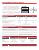
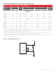
TABLE 7. PRESSURE RANGE SPECIFICATIONS (CONTINUED)
PRESSURE
RANGE
(SEE FIGURE 3.)
PRESSURE RANGE
UNIT
OVERPRESSURE
1
BURST PRESSURE
2
COMMON
MODE
PRESSURE
3
PMIN. PMAX.
Port 1 (P1) Port 2 (P2) Port 1 (P1) Port 2 (P2)
1 psi to 150 psi
Differential
001PD -1 1 psi 30 10 50 15 150
005PD -5 5 psi 150 30 275 40 150
015PD -15 15 psi 250 60 275 120 250
030PD -30 30 psi 250 120 275 240 250
060PD -60 60 psi 250 250 275 275 250
Gage
001PG 0 1 psi 30 — 50 — 150
005PG 0 5 psi 150 — 275 — 150
015PG 0 15 psi 250 — 275 — 250
030PG 0 30 psi 250 — 275 — 250
060PG 0 60 psi 250 — 275 — 250
100PG 0 100 psi 250 — 275 — 250
150PG 0 150 psi 250 — 275 — 250
1
Overpressure: The maximum pressure which may safely be applied to the product for it to remain in specification once pressure is returned to the
operating pressure range. Exposure to higher pressures may cause permanent damage to the product. Unless otherwise specified this applies to all
available pressure ports at any temperature with the operating temperature range.
2
Burst pressure: The maximum pressure that may be applied to the specified port (P1 or P2) of the product without causing escape of pressure
media. Product should not be expected to function after exposure to any pressure beyond the burst pressure.
3
Common mode pressure: The maximum pressure that can be applied simultaneously to both ports of a differential pressure sensor without causing
changes in specified performance.
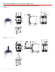
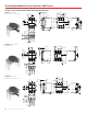
FIGURE 4. RECOMMENDED FILTER CAP
V
SUPPLY
V
SUPPLY
V
OUT
*
Ground
*Analog output version only
.
0.1 uF
0.001 uF*