ADEMCO LYNXR Series Security Systems LYNXR/LYNXR24 and LYNXR-EN Installation and Setup Guide ARMED 1 2 RECORD VOLUME OFF ESCAPE 4 AWAY ADD STAY DELETE LIGHTS ON 7 SELECT K5963V3bx 5/04 Rev.
RECOMMENDATIONS FOR PROPER PROTECTION The Following Recommendations for the Location of Fire and Burglary Detection Devices Help Provide Proper Coverage for the Protected Premises. Recommendations for Smoke and Heat Detectors With regard to the number and placement of smoke/heat detectors, we subscribe to the recommendations contained in the National Fire Protection Association's (NFPA) Standard #72 noted below.
Table of Contents SYSTEM FEATURES ...............................................................................................................................................4 MOUNTING THE CONTROL..................................................................................................................................5 WIRING CONNECTIONS........................................................................................................................................
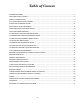
System Features UL LYNXR and LYNXR-EN are not intended for UL985 Household Fire applications unless a 24-hour backup battery (P/N LYNXRCHKIT-HC) is installed. Powerline Carrier Devices are not UL Listed for fire or burglary functions and are intended for home automation. The LYNXR-Series controls are self-contained, rechargeable wireless control/communicators that feature easy installation and usage.
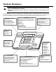
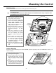
Mounting the Control Wall Mounting The illustration below shows the front assembly separated from the back plate. 1. Separate the front assembly from the back plate by pressing on the two locking tabs at the top of the unit. 2. Carefully disconnect the ribbon cable from the front assembly, leaving the ribbon cable connected to the terminal block PC board. The back plate contains the terminal block for making wiring connections.
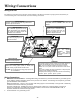
Wiring Connections Wiring Overview The following summarizes the connections required. Refer to the Wiring Connections paragraph and the Summary of Connections diagram on the inside back cover when making connections. HARDWIRE ZONE Supports 1 EOLR supervised zone using either closed circuit or open circuit sensors. LONG RANGE RADIO Compatible with the ALARMNET 7845C and 7720 Devices. POWERLINE CARRIER DEVICES Supports up to 8 Powerline Carrier Devices for turning on/off lights and appliances.
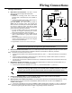
Wiring Connections Wiring Connections INCOMING PHONE LINE RING TIP RED 4 GREEN 5 3 6 TO PREMISES PHONES RJ31X 7 8 2 1 GREY RING TIP BROWN DIRECT CONNECT CORD TIP RING TIP GREY RED BROWN OR RING 8-POSITION JACK } } Make Phone Line Connections - For local or full line seizure proceed to the appropriate steps below. Local Seizure a. Connect the incoming phone line to either the 8-position jack or terminals 2 (TIP) and 3 (RING) on the Lynx. b.
Wiring Connections ALL OUTPUT CIRCUITS ARE POWER LIMITED. WARNING: TO PREVENT RISK OF SHOCK DISCONNECT TELEPHONE LINE AT TELECOM JACK BEFORE SERVICING THIS UNIT.
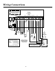
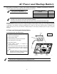
AC Power and Backup Battery The system is powered by a 9VAC, 15VA Plug-in Transformer, Canada). Refer to the wiring table below for wire gauge and length. ADEMCO 1332/1332X10 (1332CN in Distance from Transformer Use only the provided ADEMCO 1332/1332X10 or 1332CN Transformer Wire Gauge to Control Up to 75 feet #20 75 to 150 feet #18 150 to 300 feet #16 Wiring to the AC Transformer must not exceed 300 feet using 16-gauge wire.
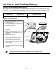
AC Power and Backup Battery AC Power and Rechargeable Backup Battery The LYNXR Series is equipped with an integral, replaceable, rechargeable battery pack composed of six (6) rechargeable 1.2-volt nickel-metal hydride batteries. Select the appropriate battery pack, based on the installation’s requirement, and install the battery pack.
Installing Wireless Zones General Information Zones: The control supports up to 24 wireless zones using 5800 Series transmitters, and up to 16 wireless buttons. Range: The built-in RF receiver can detect signals from wireless transmitters within a nominal range of 200 feet. Transmitters: 5800 Series transmitters have built-in serial numbers that must be entered into the system using the ✻56 or ✻83 interactive mode, or input to the control via the downloader.
Installing Wireless Zones Transmitter Battery Life • Batteries in the wireless transmitters may last from 4–7 years, depending on the environment, usage, and the specific wireless device being used. Factors such as humidity, high or low temperatures, as well as large swings in temperature may all reduce the actual battery life in a given installation.
Installing Wireless Zones 5800 Series Transmitter Loop Numbers (Refer to this information when programming transmitters) The following illustration shows the compatible transmitters, their associated input types and loop designations.
Mechanics of Programming General Programming Information Programming options are stored in non-removable, electrically erasable, nonvolatile EEROM memory. The system can be programmed at any time, even at the installer's premises prior to the actual installation. Simply apply power temporarily to the Control and then program the unit as desired.
Zone Response Type Definitions General Information During programming, you must assign a zone type to each zone, which defines the way in which the system responds to faults in that zone. Zone types are defined below. Type 00 Zone Not Used Type 01 Entry/Exit Burglary #1 Zone type 00 is used to program a zone that is not used. Zone type 01 is usually assigned to sensors or contacts on primary entry and exit doors. Zone Characteristics: • Entry delay #1 is programmable from 0-99 seconds (field ✻35).
Zone Response Type Definitions Type 07 24-hour Audible Alarm Type 08 24-hour Auxiliary Alarm 5806/5807/5808 Type 09 Supervised Fire 01000-020-V0 Type 10 Interior w/Delay Type 20 Arm–Stay Zone type 07 is usually assigned to a zone containing an Emergency button (audible emergency). Zone Characteristics: • Sends a report to the central station, and provides alarm sounds externally and at the keypad.
Data Field Descriptions Defaults (where applicable) are Indicated in Text. The following pages list all data fields in this Control (in numerical order). Use the blank programming form to record the data for this installation. Note that both keypad LEDs flash while in Programming mode. Note: Entering a number other than the one specified will give unpredictable results. The Installer Code is used to enter the 4-digit Master Security Code. See "Master Code" in the System Operation section for procedure.
Data Field Descriptions ✻35 Entry Delay 01 00-99 = entry delay time in seconds. The system will wait the time entered before sounding alarm upon entering if system is not disarmed. UL installations: must be set for a maximum of 45 seconds ✻36 Entry Delay 02 The system will wait the time entered before sounding alarm upon entering. UL installations: must be set for a maximum of 45 seconds ✻37 Audible Exit Warning/Quick Exit ✻38 ✻39 00-99 = entry delay time in seconds.
Data Field Descriptions Field 46: Enter up to 24 digits. Do not fill unused spaces. Enter 0-9, #+11 for ‘*’; #+12 for’#’; #+13 for a pause (2 seconds). This option allows the user to schedule a time driven message. When “Follow Me Reminder” Phone Number ✻46 ✻47 Enter up to 24 digits. Phone System Select Note: For LYNXR/LYNXR24 only options 0, 1, 2, and 3 are applicable. For LYNXR-EN all options apply.
Data Field Descriptions ✻50 15-Second Dialer Delay (Burglary) ✻51 Periodic Test Report ✻52 First test Report Offset ✻53 Sescoa/Radionics Select ✻54 Lack of Usage Notification 0 = no dialer delay 1 = provide 15-second delay of burglary alarm report when armed away 0 = no test report 1 = once every 24 hrs Test report code entered in field ✻64 is sent. 2 = weekly 3 = once every 30 days This is the time to first report from programming or downloading.
Data Field Descriptions SYSTEM STATUS REPORT CODES (✻59–✻68) If the system is armed and an entry/exit or interior zone is still open after the exit delay time has expired, an alarm will sound at the keypad and external sounder. If the system is disarmed before the end of the entry delay that immediately follows, the alarm sounding will stop and no message will be sent to the central station. The keypad will display “CA (CANCELED ALARM).
Data Field Descriptions RESTORE REPORT CODES (✻70–✻76) Continued ✻75 RF Transmitter Low Batt. Restore Code (See notes above) Sent when a transmitter that previously sent in a “low battery” message has sent a message indicating it no longer has a low battery condition. ✻76 Test Restore Report Code (See notes above) Sent when the test mode is exited. A restore code entered here will cause a restore message to be sent when Test mode is exited.
Data Field Descriptions ! The features programmed in Field ✻91 differ between LYNXR models. Ensure you use the correct option for the model you are installing! ✻91 LYNXR/LYNXR24 Long Range Radio/Alarm Audio Verification (AAV) Trigger/Remote Phone Control 0 = long range radio trigger only 1 = AAV and remote phone control 2 = long range radio trigger and remote phone control 4 = AAV only Notes: For UL installations Alarm Audio Verification cannot be used.
Data Field Descriptions Other Programming Commands ✻55 ✻56 ✻80 ✻81 ✻83 ✻84 ENABLING THE WIRELESS DIALER Interactive menu mode used for enabling the 5842 Wireless Dialer. Refer to the ✻55 Enabling the Wireless Dialer Mode section for procedure. ENHANCED ZONE PROGRAMMING MODE Interactive menu mode used for programming zone attributes and report codes. Refer to the ✻56 Enhanced Zone Programming Mode section for procedure.
✻55 Enabling the 5842 Wireless Dialer This is an interactive menu mode that is used to enable and program the 5842 Wireless Dialer. When enabled, the 5842 will interface with the Lynx Control and serve as the system’s primary dialer. The 5842 receives and acknowledges RF messages from the control’s transceiver and, in response, sends reports to the central station via the dialer. It also sends acknowledgements, supervisory and tamper RF transmissions to the control.
✻55 Enabling the 5842 Wireless Dialer While in Program mode, press ✻55 to enter Wireless Dialer Programming Feature. The following explains the ✻55 prompts in detail. The left two columns identify the prompts and list the available entries for each. The right-most column provides a further explanation of the entries. Note: You may find it convenient to adjust the volume setting before entering the Programming Mode. This will allow you to clearly hear feedback announcements or system beeps.
✻56 Enhanced Zone Programming Mode This is an interactive menu mode that is used to program zone numbers, zone types, alarm and report codes, and to identify the type of loop input device. This mode can also be used for entering 5800 Series transmitter serial numbers. Note: There are two methods for entering transmitter serial numbers. The first method is by using ✻56 Enhanced Zone Programming mode (described below). The second method is by using ✻83 Enhanced Sequential Mode.
✻56 Enhanced Zone Programming Mode While in Program mode, press ✻56 to enter Zone Programming Menu Mode. Refer to the zone assignment table for ✻56 on the separate programming form. The following explains the ✻56 prompts in detail. The left two columns identify the prompts and list the available entries for each. The right-most column provides a further explanation of the entries. Note: You may find it convenient to adjust the volume setting before entering the Programming Mode.
✻56 Enhanced Zone Programming Mode RF Learning - Two (2) transmissions (2 key depressions) at least 5 seconds apart will be required for BR type devices (device type 5). Two beeps will sound after the second transmission, confirming that the loop number and serial number have been learned. For all other device types, four (4) transmissions are required (fault, restore and fault, restore). A single beep will sound after the second transmission confirming that the loop and serial number have been captured.
✻56 Enhanced Zone Programming Mode Manual entry Enter "1" to advance to Serial number prompt (1b). Copy the previous serial number Enter “2” to copy the previous serial number entered. Return to Prompt (E) Enter “#” to return to Loop Number prompt (E). Enter transmitter later Enter “0” or “✻” if you wish to enter the transmitter later, using the ✻83 Enhanced Sequential Mode described later in this manual.
✻80 Device Programming Menu Mode Powerline Carrier devices (eg., X-10 brand devices) are programmable switches that can be used to perform many different functions. They can be used to turn lights on and off, control sounders, or for status indications. In this system, each device must be programmed as to how to act (ACTION), when to activate (START), and when to deactivate (STOP). Each of these is described below. The control supports a total of 8 output devices.
✻80 Device Programming Menu Mode The "STOP" programming determines when and under what conditions the device will be deactivated. The following options are available: Upon Restore of a Zone List Restore Zone List: If a "ZONE LIST" is used as the “Stop” event, the device will de-activate when all the zones in that list restore from a previous fault, trouble, or alarm condition.
✻80 Device Programming Menu Mode The following explains these prompts in detail. The left two columns identify the prompts and list the available entries. The right-most column provides a further explanation of the entries. Note: Entering a number other than one specified will give unpredictable results. 80 Entering “1” advances to the next prompt below. Entering “0” exits mode, upon which this prompt blinks, indicating the mode is inactive.
✻81 Zone List Menu Mode While in Program mode, press ✻81 to enter Zone List Menu Mode. This mode is used to program zone lists for output devices (programmed in ✻80 menu mode) or Chime-by-Zone in Zone List 3. NOTES: • Any list may include any or all of the systems zone numbers. • A zone list can be assigned to more than one Powerline Carrier Device.
✻83 Enhanced Sequential Mode By using this mode, you can add, delete, or change the serial number of a transmitter in a zone, but retain all other existing data that has been programmed for that zone. Note that the ✻83 Enhanced Sequential mode requires that all zone information must first be entered using the ✻56 Enhanced Zone Programming mode for all zones below zone number 26 (4 button key area).
✻83 Enhanced Sequential Mode IA IA zz LC Enroll mode 0 = advance to next zone to be enrolled 1 = enter now and proceed to SERIAL NUMBER prompt (1b). For 4 button keys (zones 26-29, 30-33, 34-37, & 38-41) the serial number will be enrolled to all four buttons. If enrolling a key, the panel will emit a long beep when entering a 1 to indicate that the present key set up is invalid. Notes: 1. A valid template or key has 4 existing zones, each with a zone type, unique loop number. 2.
✻83 Enhanced Sequential Mode Ib Ib zz Serial number Enter transmitter’s 7- digit serial number via RF learning or manually. [#] = return to (1A) prompt and reject whatever serial number entries have been made. [✻] = return to (1A) prompt (if a valid serial number has been enrolled, “L” is displayed and the serial number will be copied into EEROM and the last serial entered buffer. Note: For zones 26, 30, 34 and 38 only BR type devices can be used.
✻84 Assign Zone Voice Descriptors Use this mode to assign voice descriptors for each zone. These are the descriptors that are announced when the system announces any event involving a zone number. Each descriptor can consist of up to 3 words. Press ✻84 while in Programming mode.
✻84 Assign Zone Voice Descriptor VOICE VOCABULARY INDEX 00 ½ second pause 82 32 A ALARM ATTIC 01 33 34 35 36 B BABY BACK BASEMENT BATHROOM BEDROOM 83 C CHECK 37 38 02 03 39 04 40 05 D DELAY DOOR DEN DETECTOR DINING DINING ROOM DOOR DOWNSTAIRS DRIVEWAY 06 41 42 E EAST EIGHT EMERGENCY 43 87 44 07 45 08 46 47 F FAMILY ROOM FIRE FIRE DETECTION FIRST FLOOR FIVE FLOOR FOUR FRONT G 48 GARAGE 49 GUEST ROOM 09 GUN 50 H HALL 10 I INSIDE 51 K KITCHEN 11 52 12 13 53 L LAUNDRY LAUNDRY ROOM LIBRARY
✻85 Record Custom Voice Descriptors Use this mode to record up to 5 custom voice descriptors. Press ✻85 while in Programming mode. Note: Entering a number other than one specified will give unpredictable results. Entering “1” advances to the next prompt below. Entering “0” exits mode, upon which this prompt blinks, indicating the mode is inactive. Assign custom voice descriptors 85 A 7d 0 = exit mode 1 = enter mode Record up to 5 custom words.
Voice Prompt Programming The LYNXR Series features a quick programming mode that allows you to program the system by responding to a series of voice prompts. The Voice Prompt Programming Guide provides you with the information required to use this feature. Voice Prompt Programming Keypad Functions: The keys shown below are used to navigate through the Voice Prompt Programming Feature. 1. ESCAPE/ OFF key: Used at any time to exit the current menu and return to the previous prompt. 2.
Voice Prompt Programming Enter Voice Prompt Programming Mode: (Installer Code + 8 8 8). Follow the voice prompts to advance to the selected item in the Main Programming Menu. Add Sensors First Central Station Phone Number Second Central Station Phone Number Templates Delete Sensors First Central Station Account Number Second Central Station Account Number Expert Programming Mode Program each option as shown below.
Voice Prompt Programming To Delete Sensors Select Select Sensor to "Delete Sensors" be Deleted Press Press [SELECT] [DELETE] To Add an Emergency Pendant Select Activate Select pendant type transmitter descriptors for the "Emergency" See (5) twice programmed pendant Press Press Press [SELECT] [SELECT] [ADD] System announces (5) Pendant Type Medical Fire Silent Police Police ! When adding wireless keys, wait 5 seconds between transmissions.
Voice Prompt Programming ! All four digits of the Central Station Account number must be entered. If ten-digit format is selected, all ten digits must be entered.
Remote Programming/Control (Downloading) General Information The control panel can be remotely programmed from an IBM-compatible Personal Computer (PC), a HAYES Modem, and ADEMCO’s Compass Downloader for Windows (as specified below). UL Downloading may only be performed if a technician is at the site. Multiple security levels protect remote programming against compromise by attempts to defeat the system. 1.
Remote Programming/Control (Downloading) • Command the system to upload a copy of its resident program to the office. • Set the time • View/Modify • X-10/ Scheduling • Read: arming status, AC power status, lists of faulted zones, bypassed zones, zones currently in alarm, zones currently in trouble, and RF sensors with low battery conditions; read control’s time. Notes: (1) After the control and the PC have established valid communication, the keypad will become inactive and will display “CC.
System Operation Security Codes Installer Code The installer programs the 4-digit Installer Code initially as part of the programming procedure. The factory default Installer Code is 4-1-1-2, but may be changed in field ✻20. The Installer Code is the only code that can enter Programming mode and also, in normal operation mode, is used to enter the Master Code, which allows access to the normal functions of the system.
System Operation Keypad Functions The keypad allows the user to arm and disarm the system, and perform other system functions, such as bypassing zones. Zone and system conditions (alarm, trouble, bypass) are displayed in the display window. When an alarm occurs, keypad sounding and external sounding will occur, and the zone(s) in alarm will be displayed on the keypad. Pressing any key will silence the keypad sounder for 10 seconds (only once).
System Operation Speaker Phone Operation (LYNXR-EN Only) To place a call or answer a call using the speaker phone: [#] + To flash (switch between two calls using call waiting): To hang up and exit speaker phone mode: To enable/disable (toggle) ringer: [#] + AUX AUX NOTE The ARMED and READY LEDs blink alternately when the Speaker Phone is active.
System Operation UL Alarm audio verification cannot be used for UL installations. Alarm Audio Verification (Two-Way Voice Feature) This feature allows the central station operator to listen, talk to or conduct a two-way conversation with an individual(s) at the premises. It also assists the operator in gathering information about the nature and location of the alarm that may be helpful in responding to police and fire departments.
System Operation “Follow Me” Reminder Feature This feature allows the user to schedule a time driven message. When activated the system will dial a phone number, that the installer programs in Field ✻46, and deliver a voice message (custom words 72, 73, and 74). The LYNXR will immediately begin transmitting the voice message and will repeat the message for 45 seconds.
System Operation Trouble Conditions The word “FAULT” on the keypad’s display, accompanied by a rapid “beeping” at the keypad, indicates that there is a trouble condition in the system. Pressing any key can silence the audible warning sound. Instruct users to call for service immediately upon seeing any of the following messages. • “Fault” and “Battery” Displays • “FAULT” and one or more zone numbers indicates that a problem exists with the displayed zone(s) and requires attention.
Testing the System Test Mode After installation is completed, the security system should be carefully tested, as follows. 1. With the system in the disarmed state, check that all zones are intact. If the READY LED is not lit, press the [ ✻] key to display the faulted zone(s). Restore faulted zone(s) if necessary, so that READY LED lights. Fault and restore every sensor individually to assure that it is being monitored by the system. 2. Enter the security code and press the TEST key.
System Communication This section provides an explanation of formats this system accommodates for reporting alarms and other system conditions to the central station. The process of a successful transmission consists of both the method of communication between the control panel and the central station receiver, and the actual way the information is sent and displayed at the central station.
System Communication Report 3+1/4+1 Standard 3+1/4+1 Expanded 4+2 Alarm SSS(S) A SSSS AZ Trouble SSS(S) T Bypass SSS(S) B AC Loss SSS(S) E SSS(S) A AAA(A) Z SSS(S) T TTT(T) t SSS(S) B BBB(B) b SSS(S) E EEE(E) AC Low Battery SSS(S) L SSS(S) L LLL(L) LB SSSS LLB Open SSS(S) O SSSS OU Close SSS(S) C Test SSS(S) G Restore Alarm SSS(S) R AC Restore SSS(S) RA SSS(S) O OOO(O) U SSS(S) C CCC(R) U SSS(S) G GGG(G)g SSS(S) R RRR(R) Z SSS(S) RA SSSSRA Ac SSS(S) RL RARARA(RA)Ac SSS(S) RL
Troubleshooting Guide SYSTEM (including Wireless) SYMPTOM 1. Transmitter signal not received at control. POSSIBLE CAUSE REMEDY 1a. Transmitter not properly powered. 1a 1b. If Transmitter is 5827, House Code not set in field ✻24, or transmitter is not set to same House Code set in that field. 1b. Check code switches inside transmitter. Must match with RF House Code programmed. Check or change transmitter's battery. 1c. Transmitter is located too far from RF receiver. 1c.
Troubleshooting Guide CONTROL SYMPTOM POSSIBLE CAUSE REMEDY 1. The word “AC” is not displayed. 1a. Interrupted AC power supply. 1a. Check transformer connection and powerline circuit breaker. 2. Digital communicator message not being received. 2a. System in Test mode. 2b. Telephone connection not secure. 2c. Digital communicator malfunctioning. 2a. Remove from Test mode. 2b. Check all connections. 2c. Check with a different CONTROL PANEL. 2d. Program prefix or access code into the CONTROL PANEL.
Contacting Technical Support PLEASE, before you call Technical Support, be sure you: • READ THE INSTRUCTIONS! • Check all wiring connections. • Determine that the power supply and/or backup battery are supplying proper voltages. • Verify your programming information where applicable. • Note the proper model number of this product, and the version level (if known) along with any documentation that came with the product. • Note your ADEMCO customer number and/or company name.
Regulatory Agency Statements UL NOTICE: This is a "Grade A" residential system. FCC ID: CFS8DLLYNXREN-2 CANADA: 1748A-LYNXREN2 FCC STATEMENT THIS DEVICE COMPLIES WITH PART 15 OF FCC RULES. OPERATION IS SUBJECT TO THE FOLLOWING TWO CONDITIONS: (1) THIS DEVICE MAY NOT CAUSE HARMFUL INTERFERENCE, AND (2) THIS DEVICE MUST ACCEPT ANY INTERFERENCE RECEIVED, INCLUDING INTERFERENCE THAT MAY CAUSE UNDESIRED OPERATION.
Specifications LYNXR-Series Security Controls 1. Physical: 10-3/8” W x 7-1/8” H x 1-3/4” D 2. Electrical: VOLTAGE INPUT: 9VAC from plug-in 15VA transformer. RECHARGEABLE BACKUP BATTERY: Six 1.2-volt/cell nickel-metal hydride rated at 1100 mA. ALARM SOUNDER: Piezo = 6-14VDC, 30mA max/ Bell = 6-14VDC, 120mA max (e.g., ADEMCO’s WAVE2EX). LONG RANGE RADIO: Rated 12mA@12-volt nominal (negative trigger signal). 3.
LYNXR/LYNXR24 PROGRAMMING DEFAULT TABLES Function *20 Installer code *21 Quick arm enable *22 Keypad backlight timeout *23 Forced bypass *24 RF house ID code *25 Powerline carrier device house code *26 Chime-by-zone *27 Real-time clock display *29 Daylight saving time start/end month *30 Daylight saving time start/end weekend *31 Single alarm sounding per zone *32 Fire sounder timeout *33 Alarm bell timeout *34 Exit delay *35 Entry delay 1 (zone type 01) *36 Entry delay 2 (zone type 02) *37 Audible exit war
LYNXR-EN PROGRAMMING DEFAULT TABLES (boldface indicates defaults that differ between tables) Function *20 Installer code *21 Quick arm enable *22 Keypad backlight timeout *23 Forced bypass *24 RF house ID code *25 Powerline carrier device house code *26 Chime-by-zone *27 Real-time clock display *29 Daylight saving time start/end month *30 Daylight saving time start/end weekend *31 Single alarm sounding per zone *32 Fire sounder timeout *33 Alarm bell timeout *34 Exit delay *35 Entry delay 1 (zone type 01) *
✻56 ZONE ASSIGNMENT/ALARM REPORT CODES FOR TABLE 1 Zone No.
✻80 DEFAULT TABLE: APPLIES TO DEFAULT TABLE 4 (devices 2-7 have no default values) Start Zone Type Restore of Device Number Action Event Zone List System Operation Zone List 1 8** 2 2 2 1 Stop Zone type System operation 2 33 36 ** NOTE: If using an X-10 Powerhouse Security SH10A siren as device 8, you must change the device action default to “3” if using default table 4.
–Index – *55 Enabling the 5842 Wireless Dialer ................................... 25 *56 Enhanced Zone Programming Mode................11, 20, 24, 27 *80 Device Programming Menu Mode....................24, 31, 32, 33 *81 Zone List Menu Mode.................................................. 24, 34 *83 Enhanced Sequential Mode ........... 24, 27, 29, 30, 35, 36, 37 *84 Assign Zone Voice Descriptors .........................24, 30, 38, 39 *85 Record Custom Voice Descriptors ...............................
Low Battery Report Code.........................................................21 Low Battery Restore Report Code ............................... 21, 61, 62 Low Speed ................................................................................54 LYNX-DM...................................................................................5 LYNXR/LYNXR24 Programming Default Tables ...................61 LYNXRCHKIT-HC...................................................................10 LYNXRCHKIT-SC .........
Remote Programming .............................................................. 45 Remote Programming/Control........................................... 45, 46 Replacing the Rechargeable Battery ....................................... 10 Report Code........................................................................ 20, 28 Report Code Formats ............................................................... 54 Report Format..............................................................
-Notes- – 68 –
WARNING THE LIMITATIONS OF THIS ALARM SYSTEM While this System is an advanced design security system, it does not offer guaranteed protection against burglary, fire or other emergency. Any alarm system, whether commercial or residential, is subject to compromise or failure to warn for a variety of reasons. For example: • Intrusion detectors (e.g., passive infrared detectors), smoke detectors, and many other sensing devices will not work without power.
LIMITED WARRANTY Honeywell International Inc.
NOTE: Connection of the fire alarm signal to a fire alarm headquarters or a central station shall be permitted with the approval of the local authority having jurisdiction. The burglar alarm signal shall not be connected to a police emergency number. The System must be checked by a qualified technician once every three years.
165 Eileen Way, Syosset, New York 11791 ‡K5963V3oŠ K5963V3bx 5/04 Rev. A Copyright © 2004 Honeywell International Inc. www.honeywell.