
Programming Manual
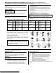

Wireless Key Programming Templates (press the [D] key from *58 Menu mode Summary Screen)
This procedure programs the wireless keys, but a key is not active for arming/disarming until it is assigned to a user number (see
System Operation
section, Assigning Attributes Command in the Installation Instructions).
TEMPLATE ?
Enter desired template number 1–6 (see chart below), then press [∗] to
continue.
To exit the Template screen, press [#]. The system returns to the *58 Menu
mode Summary Screen.
TEMPLATE SUMMARY
L 01 02 03 04
T 23 22 21 23
The selected template is displayed.
The top line represents loop numbers, the bottom line represents each
loop’s zone type.
Press [∗] to accept template and continue.
PARTITION (VISTA-20P)
Enter the partition (1, 2, or 3-common) in which the key is to be active.
Press [∗] to continue.
ENTER START ZONE
The system displays the lowest zone number of the highest available
consecutive 4-zone group.
To start at a different zone number, enter the zone desired, and press [∗]. If
the system has four consecutive zones beginning with that zone, the zone
number is displayed. If not, the system will again display a suggested zone
that can be used.
If the required number of consecutive zones is not available at all, the
system will display “00”.
Press [∗] to accept.
Continue to the INPUT S/N (serial number/loop number) and XMIT TO
CONFIRM prompts described earlier in the *56 Menu Mode section.
IMPORTANT: When confirmed, the key is not active for arming/disarming
until it is assigned to a user number (using the assigning attributes command,
attribute “4”). See System Operation section in Installation Instructions.
When done, the keypad beeps three times and the display returns to the
ENTER START ZONE prompt to let you enter the starting zone for the next
wireless key.
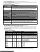
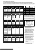
Wireless Key Predefined Default Templates
For 5804
Loop Function Zone Type
For 5804BD
Loop Function Zone Type
TEMPLATE 1 1 No Response 23 TEMPLATE 4 1 No Response 23
2 Disarm 22 2 No Response 23
3 Arm Away 21 3 Arm Away 21
4 No Response 23 4 Disarm 22
TEMPLATE 2 1 No Response 23 TEMPLATE 5 1 No Response 23
2 Disarm 22 2 Arm Stay 20
3 Arm Away 21 3 Arm Away 21
4 Arm Stay 20 4 Disarm 22
TEMPLATE 3 1 24-hour audible 7 TEMPLATE 6 1 24-hour audible 7
2 Disarm 22 2 Arm Stay 20
3 Arm Away 21 3 Arm Away 21
4 Arm Stay 20 4 Disarm 22
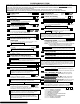
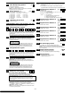
5800 Series Transmitter Input Loop Identification
All of the transmitters illustrated have one or more unique
factory assigned input (loop) ID numbers. Each of the inputs
requires its own programming zone
(e.g., a 5804's four inputs
require four programming zones).
For information on any transmitter not shown, refer to the
instructions accompanying that transmitter for details regarding
loop numbers, etc.
UL NOTE: The following transmitters are not intended for
use in UL installations: 5802MN, 5802MN2, 5804, 5804BD,
5814, 5816TEMP, 5819, 5819WHS & BRS, and 5850.
The 5827BD and 5800TM can be used in UL Listed
Residential Burglar installations.
5802MN
ENROLL AS
"UR" OR "RF"
LOOP
1
V20P-006-V
0
5817
ENROLL AS
"RF"
5890
ENROLL AS
"RF" OR "RM"
LOOP 1
5808
ENROLL AS
"RF"
LOOP 1
5809
ENROLL AS
"RF"
5850 (GBD)
ENROLL AS
"RF"
(Green)
(Red)
(Yellow)
5804BD
ENROLL AS
"BR"
LOOP 4
YOU MUST
ENROLL
THIS BUTTON
SET
HOUSE
CODE
LOOP 3
LOOP 1
LOOP 2
5804
ENROLL AS "BR"
ON
5816MN
ENROLL AS
"RF"
LOOP 2
(REED)
5816
ENROLL AS
"RF"
LOOP 1
(TERMINALS)
LOOP 2
(REED)
LOOP 3
(TERMINALS)
5819S (WHS & BRS)
ENROLL AS
"RF"
LOOP 1
(INTERNAL
SHOCK
SENSOR
LOOP 2
(REED)
5819
ENROLL AS
"RF"
LOOP 2
(REED)
LOOP 3
(TERMINALS)
LOOP 1
(TERMINALS)
5801
ENROLL AS
"UR" OR "RF"
LOOP 3
LOOP 1
LOOP 2
LOOP 4
YOU MUST
ENROLL
THIS
BUTTON
LOOP 1
LOOP 2
LOOP 4
YOU MUST
ENROLL
THIS
BUTTON
LOOP 3
LOOP
1
MOTION
LOOP 2
(AUX.
CENTER)
LOOP 1
(PRIMARY)
LOOP 3
(AUX.
RIGHT)
LOOP 1
(TERMINALS)
ALTERNATE
POSITION
FOR LOOP 2
OFF
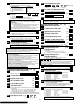
*57 Function Key Programming (press
∗
∗∗
∗
57 while in Data Programming mode)
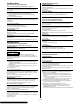
The Function Key Worksheet is on page 14.
PRESS KEY TO PGM
Press the desired function key to be programmed, A-D, then press [∗] to
continue.
When done, press 0 to exit this mode and return to data field mode.
NOTE: A key programmed as a function key is no longer available to be
used as an end-user macro key or panic key.
PARTITION
Enter the partition (1-3) in which this function key will be active.
KEY "A" FUNC
Enter the desired function for this key:
00 = For the Function key selected, the function will be as follows (default):
If A selected = Zone 95 (emergency key, same as [1] [∗] pair)
If B selected = Zone 99 (emergency key, same as [∗] [#] pair)
If C selected = Zone 96 (emergency key, same as [3] [#] pair)
If D selected = Single-button paging (continued in next column)
KEY "A" FUNC (continued)
01 = Single-button paging (sends a 999-9999 message to pager)
02 = Display time
03 = Arm AWAY (reports as User 00 if closing reports are enabled)
04 = Arm STAY (reports as User 00 if closing reports are enabled)
05 = Arm NIGHT-STAY (reports as User 00 if closing reports enabled)
06 = Step Arming (arms STAY, then NIGHT-STAY if enabled, then
AWAY)
07 = Output Device Command (for device programmed as system
operation type 66 in *80 Menu Mode)
08 = Communication Test (sends Contact ID code 601)
09 -12= Macro Keys 1-4 respectively (defined by [#] [6] [6] command)
NOTE: Macros 11-12 apply to VISTA-20P only
Press [∗] to continue; returns to key number prompt with the next function key letter
displayed.
– 9 –