
Installation Information


AM-1 SERIES™
62-3075EFS—03 2
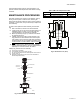
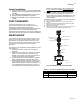
Fig. 1. AM-1 Series ASSE 1017 application
Installation of Union Sweat, CPVC
and PEX Connections
— Union sweat connections, if used, should be soldered
prior to assembly to the valve, or without the sealing
gasket or optional check valve present. After the joint
has cooled, the sealing gasket and/or check valves
may be installed.
— CPVC fittings are limited to a system maximum tem-
perature of 180° F (82° C) and 100 psi (689 kPa).
— PEX fitting and crimp ring (provided by Installer) are
deigned to meet ASTM F1807 requirements.
— PEX tubing used with PEX fittings must meet ASTM
F876 requirements.
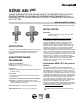
VALVE ADJUSTMENT
To adjust temperature setting of the mixing valve, attach
thermostrip (supplied with the valve) to the piping connected
to the Mix port of the valve. Loosen handwheel screw, lift
handwheel and turn to desired temperature as indicated on
the thermostrip. Reposition the hand wheel and retighten
screw.
Temperature Setting Procedure
It is possible to limit the temperature range. To use this
feature:
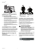
Thermostrip Installation
Clean pipe and firmly apply Thermostrip on mix outlet of
valve. Flow water and adjust mixed outlet temperature for
desired setting range. Actual mixed water temperature is
indicated in green with 2° F (1° C) increments. Blue means
slightly lower and brown means slightly higher.
WARNING
Water Temperature above 120°F (49° C) can cause
serious injury. Mixing valve temperature setting
should be done by licensed contractor per local
code requirement. To ensure correct temperature
control, use water thermometer at faucet outlet.
The thermostrip is ONE TIME USE ONLY for initial system
temperature setting. Check expiration date printed on
temperature strip to ensure temperature reading accuracy. If
necessary, contact your Honeywell distributor to obtain a
replacement thermostrip, part number TS205-064.
Fig. 2. Thermostrip.
Post Installation Procedure
1. Write temperature setting on CAUTION label and sign in
space provided.
2. Attach CAUTION label to AM-1 valve.
3. Explain CAUTION label to owner.
4. Deposit this instruction sheet with owner.
OPERATION
The AM-1 series valve provides for automatic operation
through the use of a thermostatic element in the product. The
element will control the mixing of the hot and cold supply to
M25029A
(1)
T
(1)
HEAT
TRAP
6
(152)
8
(203)
MAX
WATER
HEATER
EXPANSION
TANK
ALLOWABLE
SERVICE
VALVE
LOCATION
AM SERIES
WATER USE FIXTURES
RECIRCULATION
PUMP
M
COLD
WATER
SUPPLY
C
V
H
TO DISHWASHER
IF PERMITTED
BY CODES
T
AQUASTAT
(1)
CHECK VALVE
M27487
LOOSEN SCREW, LIFT HAND WHEEL.
TURN HAND WHEEL CLOCKWISE
OR COUNTER CLOCKWISE TO
ADJUST TEMPERATURE.
1
2
REPOSITION HAND WHEE
L
TO LOCK POSITION.
RETIGHTEN SCREW.
3
4
33
4
1
2
2
c
H
c
H