
AQ255 / AQ257 Series Quick Installation Guide
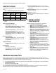
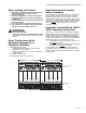

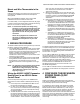
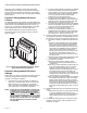
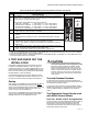
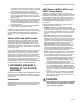
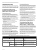
Table Of Contents
- Product Description
- Features
- Specifications
- When Installing this Product…
- Check That You Have All the Necessary Equipment For a Successful Installation
- Read All Instructions Carefully Before Proceeding
- Familiarize Yourself With the AQ255 / AQ257 Expansion Zoning Panel
- Mount Expansion Zoning Panel(s)
- Mount and Wire Thermostats in the Zones
- Wiring the AQ255 / AQ257 Expansion Zoning Panel to an AQ2000 Series Control Panel
- Startup
- Test and Checkout Routines
- Test Expansion Zoning Panels used with AQ250 Control Panels
- Test Expansion Zoning Panels used with AQ25A, AQ251, and AQ252 Control Panels
- AQ250 Models
- AQ25A, AQ251 and AQ252 models
- Job Records
- SAVE Feature (AQ25A, AQ251, and AQ252 Control Panels)
- Troubleshooting
- Appendix

AQ255 AND AQ257 SERIES EXPANSION ZONING PANELS
7 69-1981—06
5 TEST AND CHECK OUT THE
INSTALLATION
If this AQ255 / AQ257 Expansion Zoning Panel is part of a
completely new AQ2000 installation, refer to the Test and
Check Out Procedure (for a complete AQ2000 system) in the
Product Data document for the main AQ2000 Series Control
Panel. The form numbers (and models) are: 69-1974 (AQ251),
69-1986 (AQ252), or 69-2119 (AQ25A).
If this Expansion Zoning Panel is being added (as a retrofit
project) to an AQ2000 system already in operation, then only
the zones of this Panel need to be tested and checked out.
Startup
Apply power to the AQ2000 Series Control Panel only after all
of the AQ2000 components (Control Panel, thermostats,
sensors, Zoning Modules/Panels) have been wired to the other
components in the hydronic heating system (boiler, zone
valves or pumps, DHW Aquastat®, etc.).
Once powered, the AQ2000 Series Control Panel begins its
start-up routine, establishing communication with all other
AQ2000 components on the AQUATROL network.
CAUTION
Electrical Shock or Equipment Damage Hazard.
Can shock individuals or short equipment circuitry.
When line voltage is applied to an AQ255 / AQ257
Expansion Zoning Panel and the front cover of the
Panel is removed, there is a risk of electrocution. Be
careful to avoid contact with the line voltage (N and L)
terminals, either with your fingers or with metal tools
(such as a screwdriver) when power is applied to the
Control Panel.
Test and Checkout Routines
For Expansion Zoning Panels connected to AQ250 Control
Panels, continue with the “Test Expansion Zoning Panels used
with AQ250 Control Panels” section.
For Expansion Zoning Panels connected to AQ25A, AQ251, or
AQ252 Control Panels, go to “Test Expansion Zoning Panels
used with AQ25A, AQ251, and AQ252 Control Panels” on
page 8.
Test Expansion Zoning Panels used
with AQ250 Control Panels
Auto Test - AQ155 / AQ157 Zoning Modules
Auto Test operation for Zoning Modules enables the installer to
test all zones wired to the Zoning Module by sequentially
activating the zoning equipment connected to each zone
output. Each step of the Auto Test routine may be paused or
skipped by pressing the Test button.
Table 2. AQ15540B Zoning Module (Pump Zoning Module) DIP Switch Arrangement.
DIP
Switch Switch Description Label and Factory Settings
1
2
3
4
Zone Address: The positions of these 4 DIP switches define the unique address for
each zone on the AQUATROL network. For each group of 4 zones, there can be only
one DIP switch in the right hand (ON) position.
The correct DIP switch settings for each zone module are:
• First Zone (1-4) Module: 1 = ON position; 2, 3, and 4 = OFF position
• Second Zone (5-8) Module: 2 = ON position; 1, 3, and 4 = OFF position
• Third Zone (9-12) Module: 3 = ON position; 1, 2, and 4 = OFF position
• Fourth Zone (13-16) Module: 4 = ON position; 1, 2, and 3 = OFF position
5
• If set to SYNC, zone synchronization is enabled.
• If set to NOT, zone synchronization is disabled.
6
• If zone valves are normally closed (N.C.), set the NC/NO DIP switch to the OFF
position.
• If zone valves are normally open (N.O.), set the NC/NO DIP switch to the ON
position.
7
• If set to Group (ON position), the AUX Pump contacts on the Control Module are
switched when any of the zones on this Zoning Module are active.
a
• If set to - (OFF position), the AUX Pump contacts are not affected by activity on
these zones.
a
If used with an AQ250 RelayPlus Control Panel, the AQ15000B Boiler Control Module’s DIP switch #5 must be set to “GROUP”
position and DIP switch #6 must be set to “MAIN” position.
If used with an AQ25A, AQ251 or AQ252 Control Panel, the EQUIPMENT SETUP > AUXILIARY I/O > AUX PUMP menu option
on the Control Panel must be set to “GROUP.”
8
• If set to 2-stage (ON position), then 2-stage operation is activated on thermostat
inputs. The zoning module operates as two 2-stage zones.
• If set to 1-stage (OFF position), then operates as four 1-stage zones.
M23720
A
AQ15540B
Test
Diagnostic
Test
M34972
ON
12345678