
AQ255 / AQ257 Series Quick Installation Guide
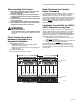
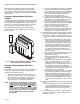
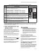
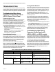
Table Of Contents
- Product Description
- Features
- Specifications
- When Installing this Product…
- Check That You Have All the Necessary Equipment For a Successful Installation
- Read All Instructions Carefully Before Proceeding
- Familiarize Yourself With the AQ255 / AQ257 Expansion Zoning Panel
- Mount Expansion Zoning Panel(s)
- Mount and Wire Thermostats in the Zones
- Wiring the AQ255 / AQ257 Expansion Zoning Panel to an AQ2000 Series Control Panel
- Startup
- Test and Checkout Routines
- Test Expansion Zoning Panels used with AQ250 Control Panels
- Test Expansion Zoning Panels used with AQ25A, AQ251, and AQ252 Control Panels
- AQ250 Models
- AQ25A, AQ251 and AQ252 models
- Job Records
- SAVE Feature (AQ25A, AQ251, and AQ252 Control Panels)
- Troubleshooting
- Appendix

AQ255 AND AQ257 SERIES EXPANSION ZONING PANELS
69-1981—06 10
TROUBLESHOOTING
The following information helps the installer correctly identify
system problems, making troubleshooting much faster. Table 3
describes the possible error codes that can be communicated
on the AQ155 / AQ157 Zoning Modules' DIAGNOSTIC LEDs.
Troubleshooting When Using
Expansion Zoning Panels with an
AQ2000 Series Control Panel
Communications Loss
Because all AQ2000 Series components communicate with
each other via the dedicated AQUATROL network when
controlling a hydronic system, one possible failure mode of an
AQ25A, AQ251, or AQ252 Control Panel would be loss of
communication between the Control Module and any
connected Zoning Modules, or between a Zoning Module and
any zone thermostats connected to the AQUATROL network.
In general, the Control Module:
• Periodically tries to re-establish communication with any lost
components on the network.
• Initializes any component that re-establishes its
communication.
• Displays an error code on the Control Panel’s System
Status page, until the error is corrected and/or
communication is re-established.
Control Module Reaction
When the AQ25A, AQ251, or AQ252 control loses
communication with any number of zones for more than one
minute (as long as there’s still at least one zone communicating
on the AQUATROL network), its Control Panel continues to
deliver heat to the other non-communicating zones and the
address of each lost zone (e.g., A-7, B-4) displays on the
Control Panel’s System Status page.
When communication is lost with all
zones, the AQ25A,
AQ251, or AQ252 enters BOILER FREEZE PROTECTION
mode, in which it fires the boiler and then activates the Boiler
(supply) pump and zone equipment for a period of 10 minutes
every hour. This should provide sufficient heat to the system to
prevent a building from freezing up until communication is re-
established between the AQ2000 Series components.
Zoning Module Reaction
When a Zoning Module loses communication with the Control
Module (as long as there is at least one other Zoning Module
communicating with the Control Module), the Zoning Module
operates its pumps or valves in a conventional, non-
synchronized zoning fashion. That is, it operates according to
the demands from the thermostats, without zone
synchronization or waiting for permission from the Control
Module to operate. This allows the zones to extract any heat
provided by the boiler.
When communication is lost between a Zoning Module and
any of its thermostats, that zone is invisible to the Control
Module. The Zoning Module stops serving that zone and the
zone’s pump or valve de-energizes. Under this condition, the
AQ2000 Series control operates in the same way as
non-networked heating systems.
• The AQ250 provides Control Module diagnostic information
via the DIAGNOSTIC LEDs located above the DIP switches
on the AQ1500 Control Module.
• The AQ25A, AQ251 or AQ252 presents Control Module
diagnostic information on the Home Page display of its LCD.
All AQ2000 Series Control Panels provide Zoning Module
diagnostic information via the DIAGNOSTIC LEDs located
above the DIP switches on their Zoning Module(s).
Troubleshooting When Using
Expansion Zoning Panels with
AQ25A, AQ251, or AQ252 models
If a zone loses communication with the Control Module or is
malfunctioning, this can be seen in the AQ25A/AQ251/AQ252
Control Panel’s System Status Page. The System Status Page
display indicates which zone has lost communication with the
Control Panel (for diagnostics and troubleshooting).
If a zone has been permanently, and intentionally,
disconnected from the network, turn off the Control Panel at
the distribution panel and wait 10 seconds. Power the control
back up and, as part of it’s boot up routine, the AQ25A/AQ251/
AQ252 will detect all equipment connected to the network. In
doing this, the control no longer recognizes the disconnected
zone and the LOST ZONE message disappears from the
System Status page.
Table 3. AQ155 / AQ157 Zoning Module LED Display and System Condition.
DIAGNOSTIC LED Status System Condition Action Required
Steady (no blinking) No system problem detected None
Fast blinking (4 blinks per second) Auto Test is in operation None. Allow the control to finish its Auto Test
routine.
Slow blinking (2 blinks every 3 seconds) Auto Test has been paused. Press the Test button to resume the Auto Test
routine.
Coded blinking = ERROR 2 blinks,
then pause
Freeze protection activated
across the entire AQUATROL
network
All zones have lost communication with the
Control Module. Check B–B wiring between the
Control Module and each Zoning Module.
3 blinks,
then pause
Communication lost with all
thermostats on the Zoning
Module
Check thermostat wiring to each Zoning
Module.