
AQ255 / AQ257 Series Quick Installation Guide
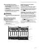
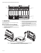
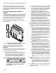
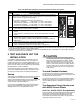
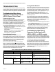
Table Of Contents
- Product Description
- Features
- Specifications
- When Installing this Product…
- Check That You Have All the Necessary Equipment For a Successful Installation
- Read All Instructions Carefully Before Proceeding
- Familiarize Yourself With the AQ255 / AQ257 Expansion Zoning Panel
- Mount Expansion Zoning Panel(s)
- Mount and Wire Thermostats in the Zones
- Wiring the AQ255 / AQ257 Expansion Zoning Panel to an AQ2000 Series Control Panel
- Startup
- Test and Checkout Routines
- Test Expansion Zoning Panels used with AQ250 Control Panels
- Test Expansion Zoning Panels used with AQ25A, AQ251, and AQ252 Control Panels
- AQ250 Models
- AQ25A, AQ251 and AQ252 models
- Job Records
- SAVE Feature (AQ25A, AQ251, and AQ252 Control Panels)
- Troubleshooting
- Appendix

AQ255 AND AQ257 SERIES EXPANSION ZONING PANELS
69-1981—06 4
Fig. 2. AQ257 Expansion Zoning Panel Layout (AQ25744B shown).
2 MOUNTING
This section describes how to mount the Expansion Zoning
Panels and thermostats.
Mount Expansion Zoning Panel(s)
1. Remove wire channel plugs from the Control Panel and
any Expansion Panels (see Fig. 3).
2. Mount Expansion Zoning Panel on the right-hand end of
the Main Control Panel.
3. Reverse wire channel plugs and re-insert them into their
slot to from a wiring channel between the Main Control
Panel and the Expansion Zoning Panel (see Fig. 3) and
to connect the two panels together.
4. Install two top screws of the Expansion Zoning Panel,
ensuring it is level with the adjoining Main Control Panel,
and install two lower screws.
5. Repeat steps 1–4 for any additional Expansion Zoning
Panels.
Fig. 3. Orientation of wire channel plugs for creating pass-through wire channel and
for joining Main Control Panel to Expansion Zoning Panels.
LOW VOLTAGE
(24 V)
LOW VOLTAGE
(24 V)
TRANSFORMER
ZONING MODULE
M27832A
Zone 1
Zone 2
Zone 3
Zone 4
LOW
VOLTAGE
(24 V)
LINE
VOLTAGE
(120 V)
M13757