
Instruction Manual


95-6571—11 G.R. Rev. 12-01 www.honeywell.com
L8124A,C,E,L AND M AQUASTAT® RELAYS
Automation and Control SolutionsAutomation and Control Solutions
Honeywell Honeywell Limited-Honeywell Limitée
1985 Douglas Drive North 35 Dynamic Drive
Golden Valley, MN 55422 Scarborough, Ontario
M1V 4Z9
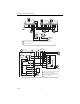
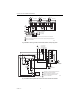
On the L8124M, the burner and circulator circuits are
separately controlled; the low limit controls the burner
circuit (R-B) as described above, while the low voltage
thermostat directly controls the circulator circuit.
See Fig. 13.
Fig. 13. L8124M single zone connections
and internal schematic.
SETTING
Follow the boiler manufacturer recommendations when
making the L8124 settings. The high limit setting must be
at least 20°F (11°C) higher than the low limit setting. Set
the indicators over the selected temperature marks. The
low limit differential is set by turning the differential
adjustment knob to the desired amount of differential.
The thermostat heat anticipator should be set at 2.0A.
CHECKOUT
Put the system into operation and observe each function
through at least one complete cycle. Be sure the control
operates as intended.
M8804
L1
(HOT)
L2
1
3
1
2
3
2
POWER SUPPLY. PROVIDE DISCONNECT MEANS
AND OVERLOAD PROTECTION AS REQUIRED.
CONTROL CASE MUST BE CONNECTED TO EARTH
GROUND. USE GROUNDING SCREW PROVIDED.
B1 IS 1/4 IN. TAB TERMINAL.
LINE VOLTAGE
OIL BURNER
RELAY OR
GAS VALVE
LINE VOLTAGE
CIRCULATOR
C2
C1
B2
B1
R
B
HIGH
LIMIT
ZC
1K1
B
R
W
LOW LIMIT
1K
L2
L1
G
TT
L8124M
LOW VOLTAGE
THERMOSTAT