
ARD Product Data

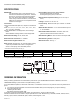
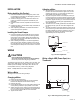

Table Of Contents

AUTOMATIC ROUND DAMPER (ARD)
3 68-0260—02
INSTALLATION
Before Installing this Product...
1. Read all instructions before installing this product. Fail-
ure to follow the instructions can damage the product or
cause a hazardous condition.
2. Check the ratings given in the instructions and on the
product to make sure the product is suitable for your
application.
3. Installer must be a trained, experienced service techni-
cian.
4. Install the product in an area that is easily accessible for
checkout and service.
5. After completing installation, use these instructions to
check out the product operation.
Installing the Round Damper
1. Insert the crimped end of the ARD into the uncrimped
end of the rigid round duct and secure with rigid sheet
metal screws (not provided). When using flexible duct,
slip the duct over the end of the ARD and secure it with
duct straps (not provided).
2. When installing the damper in a horizontal application,
make sure the motor actuator is located on the side or
top of the damper. Do not locate the motor on the bottom
of the damper.The damper can be mounted in a vertical
duct.
WIRING
CAUTION
Personal Electrical Shock Hazard.
Can cause electrical shock or equipment damage.
Disconnect power before beginning installation.
The damper motor has a 24 Vac, 50/60 cycle, 6 VA rating. The
spring-return ARD damper requires 24 Vac to the two motor
leads to power the damper. The damper then returns to its
normal position. See Fig. 3 and 4 wiring diagrams.
NOTE: Multiple ARD can be wired in parallel.
Wiring a Motor
See Fig. 3 and 4 for motor wiring hookups.
Changing a Motor
1. Disconnect the motor wiring.
2. Loosen the large socket head cap set screw located
between the faceplate and the motor coupling.
3. Remove the motor.
4. Ensure damper blade is in the open position with the set
screw pointing toward the open position on the label.
5. Attach new motor to the coupling; be sure the standoff on
motor is positioned in the grommet on the faceplate and
the set screw is aligned with the motor shaft hole.
6. Tighten the set screw.
Adjusting a Motor
1. When viewed on end, the lower lever is normally posi-
tioned to the extreme left and the upper lever is to the
extreme right. See Fig. 2. This position provides com-
plete shutoff when the damper is closed.
2. To prevent complete closure of the damper, loosen (do
not remove) the wing nut on the bottom of the motor and
move the upper lever to the left until the desired position
is reached. Tighten the wing nut. In the extreme left posi-
tion, the damper should stay open approximately 40°
when powered shut.
3. The lower lever is normally positioned to the left to allow
the damper to fully open 90° when de-energized. See
Fig. 2.
4. To restrict the air flow in the open position, loosen (do not
remove) the wing nut and move the level to the right until
the desired position is reached. Tighten the wing nut. In
the extreme right position, the damper should open
approximately 50° with the power off.
Fig. 2. Air flow adjustment.
Wiring a Single ARD (Power Open) to a
Thermostat
Fig. 3. ARD configured as power open.
UPPER LEVER
WING NUT
LOWER LEVER
M20155
Y
M24048
W
AT140 TRANSFORMER
ARD CONFIGURED
AS POWER OPEN
R
R
C
G