
Datasheet


Airflow Sensors AWM5000 Series
Highflow Mass Airflow/Amplified
80
Honeywell1 Sensing and Control11-800-537-6945 USA1F1-815-235-6847 International11-800-737-3360 Canada
SPECIFICATIONS (Performance Characteristics @ 10.0 ±0.01 VDC, 25°C)
AWM5101 AWM5102 AWM5103 AWM5104
Flow Range (Note 3) 0-5 SLPM 0-10 SLPM 0-15 SLPM 0-20 SLPM
Suffix - Calibration gas VA - Argon (Ar) VC - Carbon dioxide (CO
2
) VN - Nitrogen (N
2
)
Min. Typ. Max.
Excitation VDC 8 10±0.01 15
Power consumption (mW) — — 100
Response time (msec) — — 60
Null output VDC 0.95 1 1.05
Null output shift
−20° to 70°C— ±0.050 VDC ±.200 VDC
Common Mode
Pressure (psi) — — 50
Temperature range −20° to +70°C, (−4° to 158°F)
Weight 60 grams (2.12 oz.)
Shock ratings 100 g peak, 6 msec half-sine (3 drops, each direction of 3 axes)
Output @ laser trim point 5 VDC @ Full Scale Flow
Output voltage shift
+20° to −25°C, +20° to 70°C Suffix VA or VN ±7.0% Reading, Suffix VC ±10.0% Reading
Linearity error (2) ±3.0% Reading (max.)
Repeatability & Hysteresis ±0.5% Reading (max.)
Connector (Included)
—Four pin receptacle MICRO SWITCH (SS12143)/AMP (103956-3)
Leak rate, max 0.1 psi/min. at static condition, (Note 2)
Notes:
1. Linearity specification applies from 2 to 100% full scale of gas flow range, and does not apply to null output at 0 SLPM.
2. The AWM5000 series product has a leakage spec of less than 0.1 psi per minute at 50 psi common mode pressure. If during installation, the
end adapters are twisted with respect to the flowtube, this may compromise the seal between the o-ring and the flowtube and may cause a
temporary leak. This leak might be as high as 1 psi or might remain in specification. It will self-reseal as the o-ring takes a new set.
Approximately 85% of the leakage will dissipate in 24 hours. Within 48 hours, complete recovery will take place.
3. SLPM denotes standard liters per minute, which is a flow measurement referenced to standard conditions of 0°C/1 bar (sea level), 50% RH.
NOTICE
AWM5000—Chimney Effect
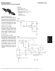
AWM microbridge mass airflow sensors detect mass airflow caused by heat transfer. The thermally isolated
microbridge structure consists of a heater resistor positioned between two temperature sensing resistors.
The heater resistor maintains a constant temperature, 160°C above ambient, during sensor operation. Airflow
moving past the chip transfers heat from the heater resistor. This airflow warms the downstream resistor and
cools the upstream resistor. The temperature change and the resulting change in resistance of the
temperature resistors is proportional to the mass airflow across the sensing element.
When the sensor is mounted in a vertical position, under zero flow conditions, the sensor may produce an
output that is the result of thermally induced convection current. This occurrence is measurable in the
AWM5000 Series, particularly in the 5 SLPM versions. When designing the sensor into applications where null
stability is critical, avoid mounting the sensor in a vertical position.