
user manual
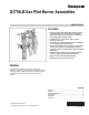
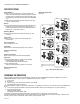
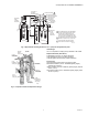

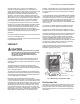
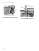
Table Of Contents

Q179A,B GAS PILOT BURNER ASSEMBLIES
60-2032—4 4
a
On some ground areas, one or more prongs were intentionally removed at the factory.
b
Orifice 0.025 in. (0.635 mm) diameter.
c
Orifice 0.0130 in. (0.330 mm) diameter (order separately).
d
Orifice 0.028 in. (0.711 mm) diameter.
INSTALLATION
When Installing this Product…
1. Read these instructions carefully. Failure to follow them
could damage the product or cause a hazardous
condition.
2. Check the ratings given in the instructions and on the
product to make sure the product is suitable for your
application.
3. Installer must be a trained, experienced, flame safeguard
control technician.
4. After installation is complete, check out product opera-
tion as provided in these instructions.
Follow instructions provided by burner manufacturer if
available. If no instructions are furnished, use the following
recommendations.
Mounting
The Q179 has two mounting ears at the burner and two
mounting holes in the bracket (see Fig. 2). If the mounting
holes in the bracket are used, it may be necessary to break off
one of the mounting ears so that the bracket fits flush with the
burner.
All models are supplied with a factory-installed 1/4 inch
compression coupling inlet fitting. When a fitting is used,
remove the compression nut and install the new fitting.
Gas Pressure Regulation
Use a pressure regulator in the line supplying the Q179 pilot.
Adjust the regulator for a maximum inlet gas pressure of eight
inches water column. The minimum inlet gas pressure must be
two inches water column to assure reliable lightoff of the main
flame.
Install the Q179A,B
Install the pilot assembly so the pilot flame has full contact with
the gas stream from the main burner heads or jets. Mount the
flame electrode just inside the junction of the main and pilot
flame to prove both flames. Mount the pilot so that it fires in the
same direction as the draft at the mounting point, rather than
where the draft is at right angles to flame travel. Keep the pilot
burner below or behind the main burner so that the burner
frame and refractory will help protect the pilot from radiant
heat. Locating the pilot in the secondary air stream will also
provide considerable cooling. The primary air adjustment must
be accessible and outside the high temperature area.
Do Not Install the Q179A,B—
— Where ambient temperatures exceed those specified in
Fig. 3.
— Where excessive draft turbulence can deflect the pilot
flame away from the main burner or flame electrode.
— Where the ignition electrode is within arcing distance of
any metal other than the pilot burner head.
— Where the flame electrode contacts any metal part of
the installation.
— Where the flame electrode is closer than one inch from
a radiant refractory.
WIRING
CAUTION
Disconnect power supply to prevent electrical
shock and equipment damage. More than one
disconnect may be involved. Wiring must conform
to local codes and ordinances.
Rajah connectors are furnished for making connections to the
ignition and flame electrodes. The ignition electrode (A models
only) takes a receptacle connector. The flame electrode (both
A and B models) takes a plug connector and has a snap-action
spring terminal.
Table 1. Additional Q179A, B Replacement Parts
Assembly Tip Style Tip
Ground and
Ground Shield
a
Orifice
Flame Rod and
Insulator AssemblyNatural Gas LP Gas
I 105063A 102464A
395390-25
b
395390-13
c
133448A
45° I 105064A 102464B
395390-25
b
133450A
45° RH 105066A 120464D
395390-25
b
133452A
45° LH 105067A 102464D
395390-25
b
133444A
T 105068A 102464F
395390-28
d
133451A
45° Y 105069A 102464C
395390-28
d
133446A
45° T 105070A 102464H
395390-28
d
133452A
Large I 121831A 102464A
395390-25
b
133448A