
Install Instructions
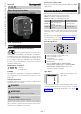

USA-2
USA
CAN
MEX
D
Installation
CAUTION
Please observe the following to ensure that the
C6097 is not damaged during installation and
operation:
– Continuous operation with gases containing
more than 0.1%-by-vol. H
2
S or ozone con-
centrations exceeding 200µg/m
3
accelerate
the ageing of elastomer materials and reduce
the service life.
– Use approved sealing material only.
– Dropping the device can cause permanent dam-
age. In this event, replace the entire device and
associated modules before use.
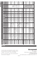
– Check max. ambient temperature – see
page5 (Technical data).
– When using silicone tubes, only use silicone
tubes which have been sufficiently cured.
– Vapours containing silicone can adversely affect
the functioning of electrical contacts.
– Condensation or vapours containing silicone
must not be allowed to get into the housing.
At subzero temperatures, malfunctions/failures
due to icing can occur.
– When installing outdoors, place the C6097 in
a roofed area and protect from direct sunlight
(even IP65 version).
– Avoid strong impact on the unit.
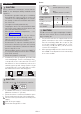
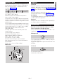
▷ Installation position as required, preferably with
vertical diaphragm. Then the switching point p
S
corresponds to the scale value SK set on the
hand wheel. In other installation positions, the
switching pointp
S
will change and no longer
correspond to the scale valueSK set on the
hand wheel. Check the switching point.
p
s
= SK
p
s
=SK + 0,08 "WC p
s
= SK - 0,08 "WC
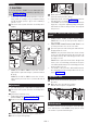
CAUTION
If port 4 is at the top, IP65 will not be satisfied.
4
IP
65
▷
The C6097 must not be in contact with masonry.
Minimum clearance 1" (25 mm).
▷ Ensure that there is sufficient installation space.
▷ Ensure unobstructed view of the hand wheel.
1 Disconnect the system from the electrical power
supply.
2 Shut off the gas supply.
3 Ensure that the pipeline is clean.
Ports
1
4
1 for
positive pressure (¼" NPT)
4 for
negative pressure (
1
/8" NPT)
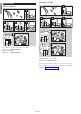
Connect Free
Positive pressure
C6097
1 4
Negative pressure
C6097
4 1
Differential pres-
sure C6097
1 for higher absolute pressure.
4 for lower absolute pressure.
CAUTION
Port 4 connects the upper diaphragm chamber
with the micro switch. Do not connect port4 to
pipes carrying gas.
▷ The pressure switches are supplied with an inte-
grated vent limiter. In the event of a diaphragm
tear, the vent limiter limits the escape of gas
to less than 1.0 CFH of natural gas at 7psi. If
necessary, port4 (1/8" NPT) can be used to
connect the venting line.
▷
A filter pad at port4 protects the electrical contacts
in the C6097 from dirt particles in the surrounding
air or in the medium.