
Install Instructions

INSTALLATION INSTRUCTIONS
® U.S. Registered Trademark
Copyright © 1996 Honeywell Inc. • All Rights Reserved
X-XX UL
C7027A1080
Minipeeper Ultraviolet Flame Detector
APPLICATION
The C7027A1080 Minipeeper Ultraviolet Flame Detector is
designed to replace these existing Honeywell and Fireye
Flame Detectors:
Honeywell: C7027A1007 and C7027A1023.
Fireye: UV-1, UV-1A, UV-2, UV-6, UV-7 and 45UV2Z.
Barber Coleman: 1292
Protection Control: P-C1 and P-C11
IMPORTANT
If replacing a Fireye, Barber Coleman or Protection
Control Flame Detector, the flame safeguard control
must also be replaced. Refer to “The Firing Line,”
form 70-8900, to select the proper Honeywell
components.
The C7027A1080 includes:
— C7027A1023 Minipeeper Ultraviolet Flame Detector;
mounting collar has 1/2-14 NPSM internal threads; 6 foot
(1.8m) leadwires; 0°F to 215°F (minus 17°C to
plus 101°C) ambient operating temperature rating.
— 136733 Heat Block, laminated plastic, for insulating the
flame detector from temperatures above 215°F (101°C);
1/2-14 NPSM external threads on one end and 1/2-14
NPSM internal threads on the other end.
— 390427B Bushing, steel pipe, for replacing a Fireye UV-2
Flame Detector; 1/2-14 external threads x 3/8-18 NPT
internal threads.
INSTALLATION
CAUTION
1. Installer must be trained and experienced in
servicing flame safeguard controls.
2. Disconnect power supply before beginning
installation to prevent electrical shock and
equipment damage.
3. All wiring must be NEC Class 1 and must comply
with applicable local electrical codes, ordinances,
and regulations.
4. Perform all required checkout tests after
installation is completed.
쐃 If replacing a Fireye Flame Detector, also replace the
Fireye Flame Safeguard Control. Refer to “The Firing
Line” form 70-8900 for instructions.
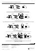
쐇 Refer to Fig. 1 and 2 for mounting dimensions and
arrangements.
60-0638-1
쐋 Disconnect the power supply and remove the leadwires
on the existing flame detector from the wiring subbase
or terminal strip.
쐏 Unscrew the existing flame detector from the sight pipe.
쐄 Clean the inside of the sight pipe.
쐂 If replacing a Fireye UV-2, Barber Coleman, or
Protection Control Flame Detector, screw the 390427B
Bushing (included) onto the sight pipe.
쐆 If the ambient operating temperature at the detector
can exceed 215°F (101°C), screw the 136733 Heat
Block (included) onto the sight pipe (or onto the
bushing when replacing a Fireye UV-2, Barber
Coleman or Protection Control Flame Detector).
쐊 Screw the C7027A1023 Detector onto the sight pipe,
heat block, or bushing, as applicable. See Fig. 1 or 2.
쐎 Connect the leadwires on the C7027A1023 Detector to
the wiring subbase or terminal strip—BLUE leadwire to
F terminal, and WHITE leadwire to G terminal.
CAUTION
The BLUE lead must be connected to the F terminal
and the WHITE lead to the G terminals. This circuit is
dc and the ultraviolet (UV) sensing tube is polarity
sensitive; reversing the leads even momentarily can
destroy the UV tube.
CHECKOUT
Conduct the tests in the Checkout section of the
accompanying Instructions for the C7027A Minipeeper
Ultraviolet Flame Detector, form 60-2026. Also conduct a
checkout of the complete system. Refer to the Checkout
section in the Instructions for the appropriate flame safeguard
control and the burner Installation Instructions, if available.
CAUTION
Do not put the system into operation until all tests in
the Checkout section of the Instructions for the
appropriate flame safeguard control and any others
specified in the burner Installation Instructions are
satisfactorily completed.
For additional specifications and instructions, refer to the
C7027A Instructions, form 60-2026.