
Submittal Sheet


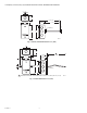
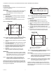
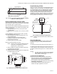
Table Of Contents

Automation and Control Solutions
Honeywell International Inc. Honeywell Limited-Honeywell Limitée
1985 Douglas Drive North 35 Dynamic Drive
Golden Valley, MN 55422 Toronto, Ontario M1V 4Z9
customer.honeywell.com
C7031B,D,G,J C7041B,C,D,F,J,K,P,R SERIES 2000 ELECTRONIC TEMPERATURE SENSORS
® U.S. Registered Trademark
© 2006 Honeywell International Inc.
63-2590—3 J.Z. Rev. 08-07
Fig. 16. Mounting sensor in conduit.
Fig. 17. Mounting sensor in wall with nut only.
Fig. 18. Mounting sensor in wall with spacer only.
WIRING
CAUTION
Erratic System Operation Hazard.
Failure to follow proper wiring practices can
introduce disruptive electrical interference (noise).
Keep wiring at least one foot away from large inductive
loads such as motors line starters, lighting ballasts,
and large power distribution panels.
Shielded cable is required in installations where these
guidelines cannot be met.
Ground shield only to grounded controller case.
CAUTION
Electrical Shock or Equipment Damage Hazard.
Can shock individuals or short equipment
circuitry.
Disconnect power supply before installation.
IMPORTANT
1. All wiring must agree with applicable codes,
ordinances and regulations.
2. Do not mount sensor in incorrect environment.
3. Wire according to the applicable controller
instructions.
OPERATION AND CHECKOUT
Operation
The C7041 Temperature Sensors are designed for use with
XL500, XL100, XL50, XL15, XL10, and Honeywell LCBS
Controllers or any controller requiring 20K ohm NTC
non-linear input. As the temperature at the C7041 Sensor
increases, the resistance of the sensor decreases, causing
the controller to operate and offset the temperature change.
Checkout
Refer to the applicable controller instructions when checking
out the complete heating and cooling systems.
To check out the sensors, move the thermostat or remote
setpoint potentiometer below the temperature of the cooling or
heating medium. Watch the motor, valve or damper for the
correct movement.
M22797
M22799
WALL
M22798
WALL