
Product Overview
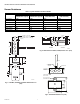
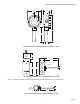
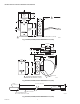
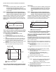
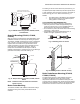
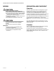
Table Of Contents

SERIES 2000 ELECTRONIC TEMPERATURE SENSORS
63-2590—06 8
IMPORTANT
To assure that the C7021J, C7023J, C7031J, C7041J
senses average duct temperature, position the
temperature elements approximately as shown in Fig.
11. Do not allow the elements to touch or be close to
the duct sides.
NOTE: When the sensor is used as a deck sensor in a
multizone system, be sure to space the elements
equally in the duct midstream as shown in Fig. 12.
Install one C7021J, C7023J, C7031J, C7041J just upstream
from the cold deck zone dampers and the other C7021J,
C7023J, C7031J, C7041J upstream from the hot deck zone
dampers. Position the thermistors to sense the average deck
temperature.
Fig. 12. Duct cross section showing method of installing
C7021J, C7023J, C7031J, C7041J in a multizone system.
C7021R, C7023R, C7041R MOUNTING
1. Install two supports inside the duct to hold the
averaging element.
2. Cut a 7/8 in. (22 mm) hole in the side of the duct.
3. Insert the averaging element into the duct through the
hole.
4. Fasten the terminal box to the outside of the duct and
thread the element through the hole and into the duct.
5. Use plastic wire ties to fasten the element to the
supports. Seal the hole around the element with a rubber
grommet.
6. Secure the end of the element to the duct on the
support to prevent continuous flexing or abrasion.
Fig. 13. Duct cross section showing method of installing
C7021R, C7023R, C7041R Averaging Electronic Sensor.
IMPORTANT
To ensure that the C7021R, C7023R, C7041R senses
average duct temperature, position the temperature
elements approximately as shown in Fig. 13. Do not
allow the elements to touch or be close to the duct
sides.
NOTE: When the sensor is used as a deck sensor in a
multizone system, be sure to space the elements
equally in the duct midstream as shown in Fig. 14.
Install one C7021R, C7023R, C7041R just upstream from the
cold deck zone dampers and the other C7021R, C7023R,
C7041R upstream from the hot deck zone dampers. Position
the thermistors to sense the average deck temperature.
Fig. 14. Duct cross section showing method of installing
C7021R, C7023R, C7041R in a multizone system.
Immersion Well Mounting (C7021D, C7023D,
C7031D, C7041D)
The C7031D Sensor includes an immersion well. The C7021D,
C7023D, and C7041D sensors do not include a well. For the
C7021D, C7023D, and C7041D, order the well as an accessory
(part no.: 50001774-001).
When used on a boiler, follow the manufacturer instructions for
location. If a tapped hole is not provided for the immersion well,
provide one as follows:
1. Drain boiler and drill a 23/32 in. (18 mm) hole at the
selected location.
2. Cut threads in the hole with a 1/2 in. (13 mm) by 14 NPT
tap.
In other installations, mount the immersion well in an elbow
with a heel outlet as shown in Fig. 15.
1. Drain the system, if you have not already done it, and
open the tapped hole.
2. Put pipe joint compound on the threads of the
immersion well and screw it into the tapped hole or
elbow, tightening it securely.
3. Refill the system and check for leaks.
Mount the C7021D, C7023D, C7031D and C7041D into the
well:
NOTE: Mounting using previously installed Honeywell
wells (part no.: 32005960-001) requires an
adapter (part no.: 50001775-001).
1. When an adapter is required, first thread it into the well
no more than one or two turns.
2. Slide the sensor into the well.
3. Rotate the sensor to thread it tightly into the adapter and
the adapter tightly into the well.
M8928
A
SENSING ELEMENTS (4)
DUCT
GROMMET
(NOT FURNISHED)
SENSOR
M22820
COPPER TUBING
WITH SENSING
ELEMENTS (4 OR 9)
DUCT
SENSOR
SUPPORTS (2)
PLASTIC
TIES (5)
NUMBER OF ELEMENTS DEPENDS
ON LENGTH OF COPPER TUBING.
1
1
M22819
DUCT
SENSOR
COPPER TUBING WITH
SENSING ELEMENTS (4 OR 9)
NUMBER OF ELEMENTS DEPENDS
ON LENGTH OF COPPER TUBING.
1
1