
Install Instructions


C7031J, C7041J,R AVERAGING SENSORS
62-0219 2
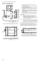
C7031J, C7041J Mounting
Fig. 1. C7031J, C7041J dimensions in in. (mm).
Fig. 2. Duct cross section showing method of
installing C7031J, C7041J Averaging Electronic
Sensor.
1. Install two supports inside the duct to hold the
averaging element.
2. Cut a 7/8 in. (22 mm) hole in the side of the duct to
insert the averaging element.
3. Fasten the terminal box to the outside of the duct
and thread the element through the hole and into
the duct.
4. Use plastic wire ties to fasten the element to the
supports. Seal the hole around the element with a
rubber grommet.
5. Secure the end of the element to the duct on the
support to prevent continuous flexing or abrasion.
IMPORTANT
To ensure that the C7031J/C7041J senses
average duct temperature, position the
temperature elements approximately as shown
in Fig. 2. Do not allow the elements to touch or
be close to the duct sides.
NOTE: When the sensor is used as a deck sensor in a
multizone system, be sure to space the elements
equally in the duct midstream as shown in Fig. 3.
Install one C7031J/C7041J just upstream from the cold
deck zone dampers and the other C7031J/C7041J
upstream from the hot deck zone dampers. Position the
thermistors to sense the average deck temperature.
Fig. 3. Duct cross section showing method of
installing C7031J/C7041J in a multizone system.
2-5/16
(59)
1(25)
1-11/16
(43)
4-3/16
(107)
4 THERMISTORS PLACED
ON A 12 FOOT (3.7M) WIRE.
4
(70)
1-11/16
(43)
M22133
M8929A
SENSING ELEMENTS (4)
DUCT
GROMMET
(NOT
INCLUDE)
SENSOR
SUPPORTS (2)
PLASTIC
TIES (5)
M8928
A
SENSING ELEMENTS (4)
DUCT
GROMMET
(NOT FURNISHED)
SENSOR