
Instruction Manual

C7110A1010 ROOM AIR QUALITY SENSOR
EN0B-0644GE51 R1109A 2
FUNCTION
The device contains a heated tin dioxide semiconductor
sensor, the electrical conductivity of which varies in proportion
to the concentration of reducing agents in the ambient air.
This leads to a voltage at the measuring element which is
amplified to an output voltage of 0 to 10 Vdc.
The following particles and gases can be detected: cigarette
smoke, hydrogen, carbon monoxide, ethanol, ammonia, etc.
In contrast to CO
2 sensors, which selectively measure the
concentration of only one type of gas, the C7110A1010 is a
mixed gas sensor and as such functions as a broadband
detector, i.e. the sensor signal does not indicate the type of
gas or its concentration in ppm (parts per million). The
complex and constantly changing composition of room air
makes it necessary to perform broadband air quality
measurement using such a broadband detector.
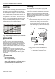
METHANE
CO
ETHANOL
HYDROGEN
INCREASING GAS CONCENTRATION
ISOBUTANE
INCREASING OUTPUT VOLTAGE
Fig. 1. Output voltage as a function of gas concentration
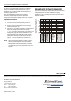
INSTALLATION
Wiring
All wiring must comply with local electrical codes and
ordinances or as specified on installation wiring diagrams.
Wall module wiring can be sized from 16 to 22 AWG (1.5 to
0.34 mm
2
), depending on the application. The maximum
length of wire from a device to a wall module is 1000 ft (305
m). Twisted pair wire is recommended for wire runs longer
than 100 ft (30.5 m).
Keep wiring at least one ft (305 mm) away from large
inductive loads such as motors, line starters, lighting ballast,
and large power distribution panels.
Run wall module wiring separately from 50 Vac or greater
power wiring.
CAUTION
Low Voltage Equipment.
Risk of equipment damage.
The 24 Vac power source for this product must be a
safety isolating transformer. A transformer that is CE
certified and meets the Low Voltage Device (LVD)
requirements must be used in Europe for all
installations of this product.
Positioning
To avoid falsifying the measuring results, the device should
be installed at sites at which typical air quality prevails.
Direct exposure to sunlight and drafts should be avoided.
If the device is mounted on a standard flush box, the end of
the installation tube in the flush box must be sealed so to
avoid any draft in the tube falsifying the measuring result.
Maintain a mounting clearance of approx. 4 in. (10 cm) to the
right-hand side of the module in order to allow free airflow to
the air quality sensor.
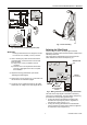
Mounting
1. The cover of the air quality sensor is fixed by a tab on
the underside of the unit; to disassemble the cover
and the sub-base, see Fig. 2. To access all of the
mounting holes, pull off the perforated cover, bend
down slightly the tab to release the printed circuit
board, and leverage the printed circuit board out (see
Fig. 3).
1
2
LIFT
PRESS
Fig. 2. Cover disassembly
2. a) Mount the sensor onto the wall outlet box,
or
b) bore wall holes as specified in Fig. 3 and mount
the wall module with appropriate screws.