
C7232 Spec Sheet
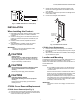
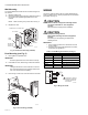
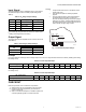
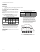
Table Of Contents

C7232A,B SENSOR AND CONTROLLER
63-2571—12 4
Wall Mounting
The C7232 Wall Mount models can be mounted using two or
four screws:
1. Remove C7232 cover.
2. Mount the subbase to the wall using washers and two or
four screws (not supplied) appropriate for the wall
material.
NOTE: When mounting on a junction box, see Fig. 4.
3. Replace the cover.
Fig. 4. Junction box mounting (C7232A).
Duct Mounting (see Fig. 5)
1. Place gasket on aspiration tube.
IMPORTANT
Ensure largest tab at tube control end is at the top.
2. Insert tube into duct; attach using screws and washers.
IMPORTANT
Leakage into the duct or the C7232 box cover from
the room will skew the sensor readings. Ensure the
box cover and duct seal completely.
3. Place O-ring on tube end; mount the control to the tube.
Fig. 5. Duct mounting (C7232B).
WIRING
The factory ships the device with the output default settings
shown in Tables 2 and 3. Set the jumpers and wire the device
(see Table 1 and Fig. 6).
CAUTION
Electrical Shock or Equipment Damage Hazard.
Can shock individuals or short equipment
circuitry.
Disconnect power supply before installation.
CAUTION
Equipment Damage Hazard.
Electrostatic Discharge Can Short Equipment
Circuitry.
Ensure that you are properly grounded before
handling the unit.
IMPORTANT
1. All low voltage connections to this device must be
24 Vac Class 2.
2. All wiring must comply with applicable local codes,
ordinances and regulations.
Table 1. C7232 Wiring Connections (see Fig. 6).
Fig. 6. Wiring the C7232.
STANDARD UTILITY CONDUIT BOX
M17542
SUBBASE
NO. 6 SCREW
NO. 6 SCREW
FRONT
COVER
BUTTON HEAD
SOCKET CAP
SCREW
M17591
FLOW
Wire Color Designation Function
Red G+ 24 V Hot
Black G0 24 V Common
Yellow OUT1 Analog Output Signal
Brown M Analog Output Common
Orange NO Relay Output Normally Open
Green COM Relay Output Common
L1
(HOT)
L2
M17543A
1
1 POWER SUPPLY. PROVIDE
DISCONNECT MEANS AND
OVERLOAD PROTECTION
AS REQUIRED.
C7232
24V
YELLOW
BLACK
RED
BROWN
ORANGE
GREEN
ANALOG
OUT
+
–