
C7232 Spec Sheet
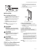
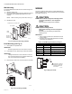
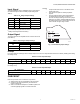
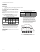
Table Of Contents

C7232A,B SENSOR AND CONTROLLER
63-2571—12 6
APPENDIX
IMPORTANT
This page is only for models with date code prior to 0309.
Pre 0309 Date Code Jumper Settings
Input Signal
The C7232 Sensors have an adjustable range. These ranges
are determined by the SW2 and OUT1 jumper settings (see
Table 6).
NOTE: When choosing analog output, be sure to set the
SW1 jumper to the On position.
Table 6. CO
2
Range Jumper Settings for models
with date code prior to 0309.
a
Setting when shipped from the factory.
b
OUT1 jumper setting does not affect the Relay Switching.
c
The analog output will not work properly when SW1 is Off.
d
When the level reaches this value, the contacts close; when
the level drops 100 ppm below this value, the contacts
open.
Output Signal
The output signal can be adjusted for 0/2-10 Vdc or 0/4-20 mA
(see Table 7).
Table 7. Output Signal Jumper Settings for models
with date code prior to 0309.
NOTES:
— On duct models with date code prior to 0309,
remove the screw holding the board in place to
view jumper settings on reverse. (See Fig. 8.)
— The CO
2
settings and the output signal settings
are independent of each other. 0-100% and 20-
100% are simply markings for the OUT jumper set-
tings on the sensor (to differentiate between the
two voltage and the two current ranges) and do not
refer to or alter the ppm range chosen.
Fig. 8. C7232 default jumper settings for models
with date code prior to 0309.
Jumper Setting
Jumper SW1 Jumper SW2
On
a
Off On
a
Off
OUT1
b
AN1 X
—
c
0 to 1000 0 to 2000
AN2
a
X
—
c
500 to 1500 500 to 2000
Relay Switching
b
X
800
d
1200
d
X
1000
d
AN1 and AN2 (set
both the same)
OUT
0-100% 20-100%
Voltage 0-10Vdc 2-10Vdc
Current 0-20 mA 4-20 mA
AN2
AN1
Current
Voltage
Current
Voltage
20 – 100%
0 – 100%
ON
OFF
ON
OFF
SW2SW1 OUT
M20494
AN2 AN1
OUT1
Select