
User Guide
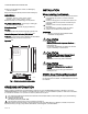
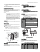
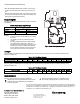
Table Of Contents

C7262A SENSOR AND CONTROLLER
3 62-0353—03
1. Insert a thin, flat blade screwdriver into each of the two
slots at the bottom of the module to release the two lock-
ing tabs.
2. Tilt the cover out and away from the subbase to release
the top two locking tabs.
Location and Mounting
C7262 Sensors mount directly on the wall, sheet metal duct, or
a panel. When planning the installation, allow enough
clearance for maintenance and service. Mount the sensor in a
well-ventilated area.
NOTES:
Do not install the sensor where it can be affected by:
— drafts or dead spots behind doors and in corners.
—air from ducts.
Sensor must be mounted in a location which sees at
lease one 4-hour unoccupied period per week so that
the CO
2
level drops to outdoor levels. Automatic
Background Calibration will not work properly in loca-
tions without four hours of unoccupied time per week,
or where there are sources of CO
2
other than people
(breweries, mushroom farms, etc).
IMPORTANT
This sensor is not for use in highly corrosive environ-
ments.
Wall Mounting
The C7262 Wall Mount models can be mounted using two or
four screws:
1. Remove C7262 cover.
2. Mount the subbase to the wall using washers and two or
four screws (not supplied) appropriate for the wall
material.
NOTE: When mounting on a junction box, see Fig. 2.
3. Replace the cover.
Fig. 2. Junction box mounting (C7262A).
WIRING
The factory ships the device with the output default settings
shown in Tables 2 and 3. Set the jumpers and wire the device
(see Table 1 and Fig. 3).
CAUTION
Electrical Shock or Equipment Damage Hazard.
Can shock individuals or short equipment
circuitry.
Disconnect power supply before installation.
CAUTION
Equipment Damage Hazard.
Electrostatic Discharge Can Short Equipment Circuitry.
Ensure that you are properly grounded before
handling the unit.
IMPORTANT
1. All low voltage connections to this device must be
24 Vac Class 2.
2. All wiring must comply with applicable local codes,
ordinances and regulations.
Table 1. C7262 Terminal Connections (see Fig. 3).
Fig. 3. Wiring the C7262.
Input Signal
The C7262 Sensors have an adjustable range. These ranges
are determined by the SW1 and SW2 jumper settings (see
Table 2).
Table 2. CO
2
Range Jumper Settings
STANDARD UTILITY CONDUIT BOX
M32569A
SUBBASE
NO. 6 SCREW
NO. 6 SCREW
FRONT
COVER
Designation Function
V+ 24V Hot
Com AC/DC 24V Common for OUT1 and OUT2
TEMP
20k ohm NTC temperature output
TEMP
OUT1: CO2 Analog Output, CO2
OUT2: CO2 Analog Output, CO2
RELAY NO
Normally Open potential free relay contacts
RELAY NO
SW1
a
SW2
a
OUT1 & OUT2 (ppm) Relay
b
(ppm)
On On 500 to 1500 1200
On Off 500 to 2000 1200
Off On 0 to 1000 1000
Off
c
Off
c
0 to 2000 800
24V
COMMON FOR
OUT1 AND OUT2
V+
24V
TEMP
TEMP
OUT1:
CO2
OUT2:
CO2
RELAY
COM
RELAY
NO
M33069A
COM AC/DC (CONVENIENCE)
COM
AC/DC
COM
AC/DC