
User Guide


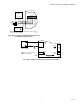


Table Of Contents

C7600A,C SOLID STATE HUMIDITY SENSORS
63-2418—06 4
INSTALLATION
When Installing this Product...
1. Read these instructions carefully. Failure to follow them
could damage the product or cause a hazardous
condition.
2. Check ratings given in instructions and on the product to
ensure the product is suitable for your application.
3. Installer must be a trained, experienced service
technician.
4. After installation is complete, check out product
operation as provided in these instructions.
CAUTION
Electrical Shock or Equipment Damage Hazard.
Can shock individuals or short equipment
circuitry.
Disconnect power supply before installation.
IMPORTANT
All wiring must agree with applicable codes,
ordinances and regulations.
Follow specific instructions furnished by the equipment
manufacturer. If unavailable, follow the procedure below.
Location
The sensor can be mounted in any position where it is exposed
to freely circulating air (with at least 500 fpm airflow) and
proper protection.
Mounting Outdoors
IMPORTANT
When selecting the location, make certain the sensor
is not exposed to rain, snow, or direct sunlight.
1. Select a location properly protected.
2. Attach the sensor to the wall with two 1/8 in. (3 mm)
diameter screws.
3. Wire as shown in the Wiring section.
Mounting in Return Air Duct (See Fig. 7)
Use the mounting instructions specific to the sensor model
series, (Series 1000 or series 2000).
Series 1000 mounting instructions
NOTE: Installers need to supply the following: sheet metal
cutter or snips; drill with 1/16 in. (2 mm), 1/8 in.
(3 mm) and 1/2 in. (13 mm) bits; screwdrivers; 1/2 in.
(13 mm) rubber grommet; eight self-tapping sheet
metal screws; and two 1/8 in. (3 mm) by 3/4 in.
(19 mm) machine screws with lock washers and nuts.
1. Cut a 5 in. (127 mm) by 6 in. (152 mm) rectangular hole
in one side of the return air duct.
2. Center the sensor on a 6 in. (152 mm) by 7 in. (178 mm)
piece of sheet metal. Mark locations for mounting screws
and for a hole for the control wire.
3. Drill two 1/8 in. (3 mm) mounting holes for the sensor
and one 1/2 in. (13 mm) hole for the control wire.
4. Drill eight starting holes in the sheet metal rectangle for
self-tapping sheet metal screws.
5. Center sheet metal rectangle over opening in duct so
there is a 1 in. (25 mm) overlap on all four sides. Then
mark the eight sheet metal screw locations on the duct.
6. Drill eight starting holes in the duct for self-tapping sheet
metal screws.
7. Attach sensor to sheet metal rectangle with 1/8 in.
(3 mm) by 3/4 in. (19 mm) machine screws, washers and
nuts. Attach machine screws from sheet metal outside to
eliminate protrusions and possible sharp edges.
8. Place a rubber grommet in the sheet metal 1/2 in.
(13 mm) hole to protect control wires from abrasions.
9. Put the control wires through the 1/2 in. (13 mm) hole
and wire as shown in the Wiring section.
10. Attach sheet metal rectangle to duct with self-tapping
sheet metal screws. Make sure that airflow over the sen-
sor is as shown in Fig. 7.
Series 2000 mounting instructions
NOTE: The series 2000 sensors can be mounted using the
duct mount sensor kit, Honeywell part number
50053060-001.
The Series 2000 sensors can be mounted directly to the sheet
metal using self tapping sheet metal screws or in the air stream
using the duct mounting kit. Use #6 or #8 screws (screws are
not provided and must be obtained separately).
Use the dimensions in Fig. 2 on page 3 as a guide. The sensor
must be mounted to allow air flow through the sensor housing
vent slots on the end or side.
The duct mounting kit contains a rod to hold the sensor in the
duct, a flange to secure the sensor rod to the duct wall and to
fill the hole, and a gasket to prevent air from leaking through
the duct wall. The rod has slots for threading the wire to
prevent loose or hanging wire in the duct and can be adjusted
for 6 or 12 inch length. The flange has extended relief for ease
of mounting.
Wiring
CAUTION
Electrical Shock or Equipment Damage Hazard.
Can shock individuals or short equipment
circuitry.
Disconnect power supply before installation.
IMPORTANT
All wiring must agree with applicable codes,
ordinances and regulations.
Follow wiring information furnished by the controller
manufacturer or refer to Fig. 5 and 6 for typical wiring hookups.
Note and follow polarity markings.