
Submittal Sheet
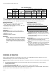


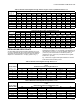
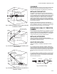
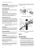
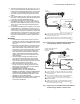
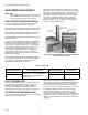
Table Of Contents
- Application
- Specifications
- Operation
- Installation
- WHEN INSTALLING THIS PRODUCT…
- BASIC REQUIREMENTS
- DETERMINE THE LOCATION
- TEMPERATURE
- SIGHTING
- FIELD OF VIEW
- CHANGING PIPE LENGTH OR SIZE (DIAMETER)
- INSTALLING AN ORIFICE PLATE
- RESPONSE TO HOT REFRACTORY
- SIGHTING SUMMARY
- CLEARANCE
- INSTALLING THE SIGHT PIPE
- PREPARE HOLE IN WALL OF COMBUSTION CHAMBER
- INSTALLING ACCESSORIES
- SIGHT PIPE VENTILATION
- SWIVEL MOUNT
- REDUCER BUSHING
- ORIFICE PLATE
- MOUNTING SIGHT PIPE
- PIPE NIPPLE
- SEAL-OFF ADAPTER
- HEAT BLOCK
- MOUNTING THE DETECTOR
- Wiring
- Adjustments and Checkout
- Troubleshooting
- Service

C7915A INFRARED FLAME DETECTOR
65-0292 10
ADJUSTMENTS AND CHECKOUT
IMPORTANT:
Before welding the sight pipe in its final location, com-
plete the Adjustments and Checkout Tests below and
any tests required by the burner manufacturer.
ADJUST DETECTOR SIGHTING POSITION
For initial burner lightoff, consult the burner manufacturer
instructions or flame safeguard control instructions.
With the flame detector installed and the burner running, adjust
the sighting position of the detector for optimum flame signal.
Refer to Table 6 for the minimum acceptable flame signal for
the amplifiers and associated flame safeguard controls.
The R7852B (AMPLI-CHECK™) amplifiers have a dc voltage
flame signal output.
To measure the flame signal voltage when using R7852A,B
amplifiers, a volt-ohm meter with a minimum sensitivity of one
megohm/volt is recommended. The flame signal (voltage)
measurements are made as shown in Fig. 12. The positive
(red) meter lead is connected to the positive (+) control jack
and the negative (black) meter lead to the negative (-)
-Com jack. If the 7800 SERIES, R7140 controls have the
Keyboard Display Module, a zero to five Vdc voltage is
displayed on the module. Refer to Table 6 for minimum and
maximum flame voltages.
Move the detector and sight pipe around to sight the flame at
various positions and angles. Try to get a maximum steady
meter reading. The signal must be above the minimum
acceptable current/voltage listed in Table 6.
Measure the flame signal for the pilot alone, the main burner
flame alone, and both together (unless monitoring only the pilot
flame when using an intermittent pilot, or only the main burner
flame when using direct spark ignition). Also measure the
flame signal at high and low firing rates and while modulating
in between (as applicable). With the detector in its final
position, all required flame signals must be steady and as
specified in Table 6. If you cannot obtain the proper signals,
refer to the Troubleshooting section.
Fig. 12. Measuring 7800 SERIES, R7140 Flame Safeguard
Control flame signal voltage.
PILOT TURNDOWN TEST
If the detector is used to prove a pilot flame before the main
fuel valve can be opened, perform a Pilot Turndown Test
before welding the sight pipe into position. Follow the
procedures in the instructions for the appropriate flame
safeguard control, and the burner manufacturer instructions.
HOT REFRACTORY SATURATION TEST
Test to be sure radiation from hot refractory does not mask the
flickering radiation of the flame itself.
Start the burner and monitor the flame signal during the
warmup period. A decrease in signal strength as the refractory
heats up indicates hot refractory saturation. If saturation is
extreme, the flame signal will decrease to a point that the
system will shut down as though a flame failure has occurred.
If hot refractory saturation occurs, the condition must be
corrected. Add an orifice plate in front of the photocell to
restrict the viewing area. If this does not work, resight the
detector at a cooler, more distant background. Lengthening the
sight pipe or decreasing the pipe size (diameter) may also be
helpful. Continue adjustments until hot refractory saturation is
eliminated.
NEGATIVE (-)
METER LEAD
POSITIVE (+)
METER LEAD
ONE MEGOHM/VOLT
METER
M7382
Table 6. Flame Signal.
Flame Signal Amplifier Flame Safeguard Control
Minimum Acceptable
Steady Voltage (Vdc)
Maximum Expected
Voltage (Vdc)
R7852A RM7800E,G,L,M; RM7823A; RM7838A,B,C;
RM7840E,G,L,M; RM7885A; RM7890A,B;
RM7895A,B,C,D; RM7896; RM7897;
RM7898; R7140
1.25 5.0
R7852B AMPLI-CHECK™ 1.25 5.0