
Submittal Sheet


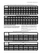
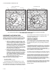
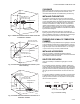
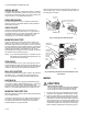
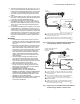
Table Of Contents
- Application
- Specifications
- Operation
- Installation
- WHEN INSTALLING THIS PRODUCT…
- BASIC REQUIREMENTS
- DETERMINE THE LOCATION
- TEMPERATURE
- SIGHTING
- FIELD OF VIEW
- CHANGING PIPE LENGTH OR SIZE (DIAMETER)
- INSTALLING AN ORIFICE PLATE
- RESPONSE TO HOT REFRACTORY
- SIGHTING SUMMARY
- CLEARANCE
- INSTALLING THE SIGHT PIPE
- PREPARE HOLE IN WALL OF COMBUSTION CHAMBER
- INSTALLING ACCESSORIES
- SIGHT PIPE VENTILATION
- SWIVEL MOUNT
- REDUCER BUSHING
- ORIFICE PLATE
- MOUNTING SIGHT PIPE
- PIPE NIPPLE
- SEAL-OFF ADAPTER
- HEAT BLOCK
- MOUNTING THE DETECTOR
- Wiring
- Adjustments and Checkout
- Troubleshooting
- Service

C7915A INFRARED FLAME DETECTOR
7 65-0292
Fig. 4. C7915A Infrared Flame Detector aimed at side wall
of combustion chamber.
Fig. 5. C7915A Infrared Flame Detector aimed at a point
above refractory.
Fig. 6. C7915A Infrared Flame Detector aimed at floor of
combustion chamber.
CLEARANCE
Make sure there will be enough room to easily mount the sight
pipe, flame detector, and all required accessories, and to
remove the flame detector for troubleshooting and servicing.
INSTALLING THE SIGHT PIPE
The location of the sight pipe is the most critical part of the
installation. A 3/4 in. black iron sight pipe is recommended. Do
not use a stainless steel or galvanized pipe because its internal
surface blackens with use as deposits from the combustion
chamber accumulate on it. Initially, its shiny internal surface
reflects infrared radiation, which could result in a satisfactory
flame signal even though the pipe may be improperly located.
As it blackens, less infrared radiation is reflected and the flame
signal becomes marginal.
Because no two situations are the same, the length and
sighting angle of the pipe must be determined at the time and
place of installation. Generally, it is desirable to have the sight
pipe tilting downward to prevent soot or dirt buildup.
PREPARE HOLE IN WALL OF COMBUSTION
CHAMBER
Form a hole of the proper diameter for the sight pipe in the wall
of the combustion chamber at the selected location. Flare the
hole (Fig. 9) to leave room for small adjustments of the sighting
angle. The taper of the hole should be about 1 in. for every 3
in. (25.4 mm for every 76.2 mm) of wall thickness.
INSTALLING ACCESSORIES
It may be necessary or desirable to install accessories
between the sight pipe and the detector. This section describes
the installation of these accessories.
SIGHT PIPE VENTILATION
It may be necessary to ventilate the sight pipe to cool the
detector.
For a negative pressure combustion chamber, drilling a few
holes in the section of the sight pipe outside of the combustion
chamber allows air at atmospheric pressure to flow through the
sight pipe into the chamber. A perforated pipe nipple between
the sight pipe and the flame detector can also be used. See
Fig. 7.
For a positive pressure combustion chamber, connect a supply
of pressurized air from the burner blower to flow through the
sight pipe into the chamber. The air pressure must be greater
than the chamber pressure.
Fig. 7. Forced air cooling.
M23454
C7915A SIGHTING
TOWARD SIDE WALL
INTERSECTION OF
PILOT AND MAIN FLAME
MAIN BURNER FLAME
REFRACTORY WALL
AREA VIEWED BY C7015A
BURNER
FACEPLATE
CENTER LINE
M23455
C7915A
SIGHTING
UPWARD
INTERSECTION OF
PILOT AND MAIN FLAME
MAIN BURNER FLAME
DETECTOR VIEWS AREA
ABOVE THE REFRACTORY
BURNER
FACEPLATE
CENTER LINE
M23457
C7915A SIGHTING
DOWNWARD (MUST
BE OFF TO THE SIDE)
INTERSECTION OF
PILOT AND MAIN FLAME
MAIN BURNER FLAME
REFRACTORY FLOOR
AREA VIEWED BY C7915A
BURNER
FACEPLATE
CENTER LINE
DETECTOR PIPE NIPPLE PIPE TEE
SIGHTING
PIPE
COOLING AIR
APPLIED UNDER PRESSURE
M3047A