
Submittal Sheet
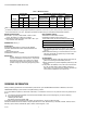


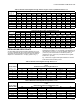
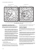
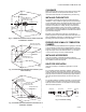
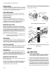
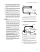
Table Of Contents
- Application
- Specifications
- Operation
- Installation
- WHEN INSTALLING THIS PRODUCT…
- BASIC REQUIREMENTS
- DETERMINE THE LOCATION
- TEMPERATURE
- SIGHTING
- FIELD OF VIEW
- CHANGING PIPE LENGTH OR SIZE (DIAMETER)
- INSTALLING AN ORIFICE PLATE
- RESPONSE TO HOT REFRACTORY
- SIGHTING SUMMARY
- CLEARANCE
- INSTALLING THE SIGHT PIPE
- PREPARE HOLE IN WALL OF COMBUSTION CHAMBER
- INSTALLING ACCESSORIES
- SIGHT PIPE VENTILATION
- SWIVEL MOUNT
- REDUCER BUSHING
- ORIFICE PLATE
- MOUNTING SIGHT PIPE
- PIPE NIPPLE
- SEAL-OFF ADAPTER
- HEAT BLOCK
- MOUNTING THE DETECTOR
- Wiring
- Adjustments and Checkout
- Troubleshooting
- Service

C7915A INFRARED FLAME DETECTOR
65-0292 8
SWIVEL MOUNT
To facilitate flame sighting, a Swivel Mount (part no. 118367A)
is available. The Swivel Mount requires a reducer of the proper
size to mount it onto the sight pipe. (For mounting details, refer
to form 60-0361 for the 118367A Swivel Mount.)
REDUCER BUSHING
To mount the detector on a 1/2 in. sight pipe, specifically if
replacing a Fireye™ lead sulfide detector, install a 390427A
Reducer Bushing (Fig. 1).
ORIFICE PLATE
To reduce the detector field-of-view, and restrict it to the
intersection of the pilot and main flame, or to a small area of
hot refractory (see Fig. 3), install a 105134 Orifice Plate. The
orifice plate can be inserted into a standard 3/4 in. pipe
coupling (Fig. 1) or into the seal-off adapter, if used.
MOUNTING SIGHT PIPE
Thread one end of the pipe to fit the mounting collar on the
detector (or an accessory, if used, see Fig. 1). Cut the pipe to
the desired length (as short as practical). To avoid conducting
excessive heat back to the lead sulfide photocell, the sight pipe
should not extend more than halfway into the refractory. Tack
weld the pipe to the wall in a trial position (Fig. 9). Do not
permanently weld the sight pipe in place until after completing
the Adjustments and Checkout, page 10.
NOTE: If you use a Swivel Mount (part no. 118367A) and you
are positive about the location and sighting angle, you
can permanently weld the pipe.
PIPE NIPPLE
A 3/4 in. pipe nipple, 6 to 8 in. (152 to 203 mm) long, can be
inserted between the sight pipe and the C7915A Mount (Fig. 1)
to help cool the lead sulfide cell. Using the pipe nipple will also
reduce the viewing area of the detector (see Table 2 or 3).
SEAL-OFF ADAPTER
To protect the detector from hot gases, install a 105172A Seal-
Off Adapter (Fig. 1). The adapter has a glass window that
prevents hot gases from reaching the lead sulfide photocell.
HEAT BLOCK
To insulate the detector from sight pipe temperatures above
125°F (52°C), install a 105061 Heat Block (Fig. 1). The device
is made of non–heat-conductive, laminated plastic that
prevents heat from being conducted from the sight pipe to the
detector. It can withstand temperatures up to 250°F (121°C).
MOUNTING THE DETECTOR
Before mounting the C7915A, install the lead sulfide photocell
(if not installed already).
Unscrew the bushing from the cap, plug the photocell into the
cell mount, and screw the bushing back into the cap (Fig. 8).
The bushing also includes a focusing lens to concentrate
available radiation on the photocell face.
Mount the C7915A Detector onto the sight pipe, heat block, or
other accessory (Fig. 1 and 9). Screw the mounting collar onto
the sight pipe or accessory.
Fig. 8. Installing lead sulfide photocell.
Fig. 9. Mounting C7915A Infrared Flame Detector (and
accessories).
WIRING
CAUTION
Electrical Shock Hazard.
Disconnect power supply before beginning installation
to prevent electrical shock and equipment damage,
there may be more than one disconnect involved.
1. All wiring must comply with applicable electrical codes,
ordinances, and regulations. Use NEC Class 1 wiring.
2. Keep the coaxial cables from the flame detector to the
flame safeguard control subbase as short as possible.
Capacitance increases with coaxial cable length, reduc-
ing the signal strength. The maximum permissible coax-
ial cable length is fifty feet. The ultimate limiting factor in
coaxial cable length is the flame signal current/voltage.
Refer to Table 6, Adjustments and Checkout, page 10.
FLEXIBLE
METAL CABLE
SHIELD LEADWIRES
PHOTOCELL
SOCKET
PLUG-IN LEAD SULFIDE CELL
(PART NO. 32007255-001)
BUSHING
MOUNTING
COLLAR
CAP
M23449
FOCUSING LENS
COMBUSTION
CHAMBER WALL
REFRACTORY
MAIN FLAME
FLARED HOLE
3/4 INCH BLACK
IRON SIGHTING PIPE
3/4 INCH
PIPE
NIPPLE
TO JUNCTION
BOX OR SUBBASE
HEAT
BLOCK
PILOT
TEMPORARY
TACK WELD
ORIFICE PLATE
IN PIPE COUPLING
SEAL-OFF
ADAPTER
C7915A
M23458