
Submittal Sheet
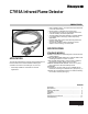


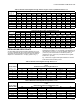
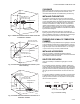
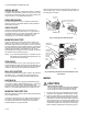
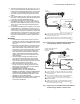
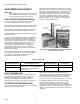
Table Of Contents
- Application
- Specifications
- Operation
- Installation
- WHEN INSTALLING THIS PRODUCT…
- BASIC REQUIREMENTS
- DETERMINE THE LOCATION
- TEMPERATURE
- SIGHTING
- FIELD OF VIEW
- CHANGING PIPE LENGTH OR SIZE (DIAMETER)
- INSTALLING AN ORIFICE PLATE
- RESPONSE TO HOT REFRACTORY
- SIGHTING SUMMARY
- CLEARANCE
- INSTALLING THE SIGHT PIPE
- PREPARE HOLE IN WALL OF COMBUSTION CHAMBER
- INSTALLING ACCESSORIES
- SIGHT PIPE VENTILATION
- SWIVEL MOUNT
- REDUCER BUSHING
- ORIFICE PLATE
- MOUNTING SIGHT PIPE
- PIPE NIPPLE
- SEAL-OFF ADAPTER
- HEAT BLOCK
- MOUNTING THE DETECTOR
- Wiring
- Adjustments and Checkout
- Troubleshooting
- Service

C7915A INFRARED FLAME DETECTOR
9 65-0292
3. The detector comes with 30, 48, or 96 in. (0.76, 1.22, or
2.44 m) coaxial cable inside a flexible metal cable. The
coaxial cable is terminated with two leads—one blue and
one white. The coaxial cable is rated for 194°F (90°C).
The cable protects and electrically shields the coaxial
cables.
4. If the coaxial cables are not long enough to reach the ter-
minal strip or wiring subbase, make the required splices
in a junction box (see IMPORTANT below).
5. If splicing is necessary, use moisture-resistant no. 14
wire suitable for at least 167°F (75°C) if the detector is
used with a flame safeguard primary control, or at least
194°F (90°C) if used with a flame safeguard program-
ming control.
6. For splicing in high temperature installations, use Honey-
well specification no. R1298020 or equivalent for the F
coaxial cable. (This wire is rated up to 400°F [204°C] for
continuous duty. It is tested for operation up to 600 volts
and breakdown up to 7500 volts.) For the other coaxial
cable, use moisture-resistant no. 14 wire selected for a
temperature rating above the maximum operating tem-
perature.
IMPORTANT:
a. Flame detector coaxial cables must be as short as
possible. The maximum coaxial cable length from the
flame detector to the flame safeguard control is 50 ft
(15.2 m).
b. Extensions to the flame detector coaxial cables must
be run alone in either rigid or flexible metal conduit.
When flame detector coaxial cables exit a conduit,
they must be as short as possible, twisted, and not be
included in bundles or channels that contain other
wires. Rigid metal conduit is preferred when flame
detector coaxial cables are extended but flexible
metal conduit may be used if it is supported to mini-
mize movement.
c. The flame detector flexible cable shield must be
grounded to the flame safeguard control subbase
either directly or through the metal cabinet/conduit
system that contains the flame safeguard control sub-
base and flame detector coaxial cables.
d. When flame detector coaxial cables are routed
through junction boxes, identify the junction boxes
with the pressure-sensitive labels provided with the
flame detector (form 96-610).
e. UNDERWRITERS LABORATORIES INC.
REQUIRES THAT THE JUNCTION BOX BE
MARKED TO INDICATE THAT NO OTHER WIRING
CONNECTIONS CAN BE ROUTED THROUGH IT.
APPLY CAUTION STICKER (FORM 96-610, FUR-
NISHED) TO THE JUNCTION BOX.
f. Maximize the separation between ignition transformer
high voltage wires and the flame sensor wires to
avoid ignition interference.
Fig. 10. Typical wiring of C7915A Infrared Flame Detector
to nearby wiring subbase or terminal strip.
Fig. 11. Typical wiring of C7915A Infrared Flame Detector
to distant wiring subbase or terminal strip.
F
G
1 BLUE WIRE AND 1 WHITE WIRE FROM THE C7915, CONNECT TO
FLAME SAFEGUARD CONTROL'S SUBBASE, KEEP WIRES AS SHORT
AS POSSIBLE, AND TWIST THEM.
FLEXIBLE CABLE MUST BE RUN TO FLAME SAFEGUARD CONTROL'S
SUBBASE AND GROUNDED WHERE THE EXPOSED WIRES BEGIN.
WIRING SUBBASE
OR TERMINAL STRIP
FLEXIBLE CABLE (MECHANICALLY
SUPPORT TO MINIMIZE MOVEMENT)
GROUNDING
STRAP
C7915A
ASSEMBLY
2
1
2
1
M23446
BLUE
WHITE
F
G
FLEXIBLE CABLE (MECHANICALLY
SUPPORT TO MINIMIZE
MOVEMENT)
C7915A
ASSEMBLY
2
1
CONDUIT
FITTING
BX CABLE, SHIELDED CABLE,
OR TWISTED PAIR; MUST BE
ALONE IN CONDUIT.
FLAME SAFEGUARD
CONTROLS SUBBASE
JUNCTION BOX
3
4
2
1
3
4
1 BLUE WIRE AND 1 WHITE WIRE FROM THE C7915; CONNECT
INSIDE JUNCTION BOX; LEADWIRES FROM JUNCTION BOX NEED
TO BE POLARIZED.
APPLY CAUTION STICKER, FORM NO. 96-610 SUPPLIED WITH
C7915, TO THIS JUNCTION BOX. BOX MUST BE GROUNDED.
USE RIGID CONDUIT, OR SUPPORT FLEXIBLE CONDUIT TO
MINIMIZE MOVEMENT.
CONDUIT MUST BE RUN TO FLAME SAFEGUARD CONTROL'S
SUBBASE AND GROUNDED THERE. KEEP EXPOSED WIRES AS
SHORT AS POSSIBLE AND TWIST THEM.
M23447