
Install Instructions
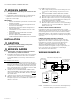
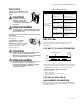
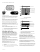
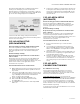
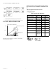
Table Of Contents

CS/CSP/MCS SERIES CURRENT SWITCHES
31-00432M—01 4
The sensor scale is pre-calibrated for motors operating at
a minimum of 75% FLA.
On startup, the sensor output will close when monitored
current exceeds 70% FLA, and open if current is below
60% FLA to indicate load loss (broken belt, coupling
shear, etc.)
For lightly loaded (oversized) motors operating below 75%
FLA, the sensor should be set to actual FLA to ensure
positive status detection and avoid nuisance alarms.
Smaller (less than 5HP) motors and/or lightly loaded
motors may not have sufficient reduction in amperage
(below 60% FLA) for the sensor to detect belt loss
immediately. The sensor will detect the belt loss when the
motor is restarted, as long as the unloaded motor current
is below 70% FLA.
For improved performance on small and lightly loaded
motors, consider the following options:
1. Use lower current models CSP-NO-A-100A or MCS-
NO-A-50A for improved calibration resolution.
2. Perform conventional calibration.
CSP-NO-A / MCS-NO-A
CONVENTIONAL CALIBRATION
Follow all safety precautions outlined in this manual.
Follow ALL requirements in NFPA 70E for safe work
practices and for Personal Protective Equipment (USA)
and other applicable local codes when installing this
product.
Read all warnings carefully.
Respectez toutes les précautions de sécurité décrites
dans ce manuel.
Respectez TOUTES les exigences de la norme NFPA 70E
concernant les pratiques de travail sécuritaires et les
équipements de protection individuelle (États-Unis), ainsi
que les autres codes locaux applicables lors de
l’installation de ce produit.
Lisez attentivement tous les avertissements.
1. Adjust knob on sensor to maximum FLA. (Fully
clockwise)
2. With motor operating normally, adjust knob SLOWLY
counter-clockwise until “Hi” LED is lit.
Fig. 1. Normal Operation
1. Set knob to motor FLA.
Fig. 2. Small / Lightly Loaded Motor Operation
1. Set knob proportionally below FLA.
2. Belt loss will be detected on restart.
3. Perform Conventional Calibration for best results.
ECM MOTOR APPLICATIONS
ECM stands for Electrically Commutated Motor. These
motors are gaining popularity due to their energy savings
capability for applications that don’t require the motor to
always run at full speed by allowing the end-user to reduce
the speed of the motor.
It is important to consider the quiescent or stand-by
current draw of an ECM from the on-board electronics.
This stand-by current draw typically ranges from 250mA
to 500mA and varies by manufacturer.
This stand-by current can sometimes be enough to cause
a sensitive current sensor to be in the ON state even when
the motor is not actually running giving a false indication.
In order to prevent this the current sensors turn-on
current must be higher than the ECM stand-by current.
Motor Nameplate
MODEL 2345 HP 10
KW 7.5 RPM 3450
Hz 60 AMP 28.4
PH 3 S.F. 1.15
RPM 345
0
SF 115
100%
85%
75%
70%
Motor FLA
Normal Run Range
(Closed above this level)
Sensor Threshold
(Open below this level)
60%
}
OFF
Normal Alarm Range
55%
35%
BELT LOSS
40%
5-20HP
20-100HP
>
>
1-5HP
}
100%
85%
75%
70%
Motor FLA
Normal Run Range
(Closed above this level)
Sensor Threshold
(Open below this level)
60%
}
OFF
Normal Alarm Range
55%
35%
<- BELT LOSS
40%
5-20HP
20-100HP
>
>
1-5HP
}