Honeywell/20 Programmable Thermostat OWNER’S GUIDE Weekday/Weekend (5-day/2-day) Programmable Heat and/or Cool Low Voltage (20 to 30 Vac) Thermostat and Mounting Plate Model CT2095 Place Bar Code Here 69- 1385
Welcome to the world of comfort and energy savings with your new Honeywell Programmable Thermostat. MERCURY NOTICE If this thermostat is replacing a thermostat that contains mercury in a sealed tube, do not place your old thermostat in the trash. Dispose of properly. Your new thermostat will automatically control the temperature in your home, keeping you comfortable while saving energy when programmed according to the instructions in this manual.
Contents Step 1. Prepare for Installation ..................................................................................................... Step 2. Remove Old Thermostat .................................................................................................. Step 3. Install Batteries ................................................................................................................ Step 4. Program Thermostat .........................................................................
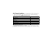
Step 1. Prepare for Installation ❑ Check Table 1 to make sure this thermostat is compatible with your system. If not, return it to the retailer. For more information, call Honeywell Consumer Services, 1-800-468-1502, Monday Friday, 7 am to 5:30 pm, Central time. Gas—Standing Pilot Gas—Electronic Ignition Gas-Fired Boilers Gas—Millivolt Table 1. Compatibility Information.
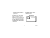
❑ Acquire tools and items as needed (see illustration). Also purchase two AA alkaline batteries; we recommend Energizer® batteries.
Step 2. Remove Old Thermostat ❑ Loosen screws holding thermostat to subbase, wallplate or wall, and lift away. ❑ Disconnect wires from old thermostat or subbase. As you disconnect each wire, attach one of the enclosed labels to each old terminal designation. If there are only two wires, they do not need labeling. If there is an extra wire that is not connected to your old thermostat, you also do not connect it to your new thermostat.
Replacing a Clock Thermostat that has C or C1 Clock Terminals? those systems so return the product to the retailer. If you want information about the programmable thermostats that work with your system, call Honeywell Consumer Services at 1-800-468-1502. If you are replacing a Honeywell Chronotherm® Thermostat, you may find one or two wires that go to the C or C1 clock terminals on the Chronotherm® Thermostat wiring wallplate. Do not allow them to touch, or you can damage your transformer.
Step 3. Install Batteries IMPORTANT Batteries must be installed for the programming and operation of the thermostat and heating/cooling system. ❑ Purchase two AA alkaline batteries; nonalkaline batteries do not last as long, and can leak, causing damage to the thermostat or the wall surface. We recommend Energizer® batteries. ❑ Open the top cover of thermostat to access control panel and battery compartment. ❑ Make sure the thermostat is set to the Off position. ❑ Use a coin to remove the battery cover.
❑ Install the fresh batteries as shown, making sure positive and negative terminals are oriented correctly. ❑ Replace the battery cover. After the batteries are completely dead, the bAtLo indication disappears, leaving a completely blank display. As the batteries run low, a bAt Lo indicator flashes for one to two months before the batteries run out completely. Replace the batteries as soon as possible after the indicator starts flashing.
IMPORTANT Although the thermostat has a low battery indicator, replace the batteries once a year to prevent the thermostat and heating/cooling system from shutting down due to lack of battery power. Press down on the left ends of batteries to remove them. If you insert the new batteries within 20 to 30 seconds of removing the old ones, you do not need to reprogram the thermostat. However, if the display is blank, the batteries are dead or incorrectly installed and you must reprogram. See Step 4.
Step 4. Program Thermostat • WAKE is the time period you want the house at a comfortable temperature when you get up and while you get ready for work or school. (This is a higher temperature during heating season and a lower temperature during cooling season.) • LEAVE is the time period you can set for an energy-saving temperature while you are away at work or school. (This is a lower temperature during heating season and a higher temperature during cooling season.
Set one schedule for weekdays and another for weekends because your requirements are usually different for each. Also, during weekends, only the WAKE and SLEEP time periods are available. If no program is entered for the weekends, the thermostat operates on the weekday SLEEP program all weekend. Before programming, remove the clear plastic overlay covering the display. Fill in the times and temperatures you desire for weekdays and weekends.
Table 2. Personal Programming Chart for Heating. Days of Week Heating Program Start Time Heating Temperaturea Weekdays WAKE LEAVE RETURN SLEEP Weekendsb WAKE SLEEP a b The temperatures cannot be set any higher than 88°F (31°C) or any lower than 45°F (7°C). If you decide not to enter weekend programs, the thermostat operates on the weekday SLEEP program all weekend.
. Table 3. Personal Programming Chart for Cooling. Days of Week Cooling Program Start Time Cooling Temperaturea Weekdays WAKE LEAVE RETURN SLEEP Weekendsb WAKE SLEEP a b The temperatures cannot be set any higher than 88°F (31°C) or any lower than 45°F (7°C). If you decide not to enter weekend programs, the thermostat operates on the weekday SLEEP program all weekend.
NOTE: Batteries are required for operation and programming. When inserting batteries, set the System switch to Off. Remove the battery door (on the thermostat left side) using a coin at the bottom. Follow instructions in Step 3. Also see the label inside the battery cover for abbreviated programming procedures for your thermostat. Set Current Time/Day Time Clock/Day To set time, press and release once, press until current shows.
Time Weekend Press until SAT SUN (Saturday-Sunday), WAKE and SET appear on display. Use to program TEMP WAKE time and to program WAKE temperature for SAT SUN (Saturday-Sunday). Run Program Repeat sequence for SLEEP. Press and release to start the program. Cooling Program With System switch at Cool, follow the same instructions as for the Heating Program. Run Program After programming, adjust the Fan and System switches, as desired. Press and release start the program.
Operating Your Thermostat System switch must be set to Heat or Cool to perform the following: TEMP Temporarily Change Temperature for current period only — Press ; temporary indicator shows Run Program on display and cancels itself at the next scheduled change; to cancel sooner, press . TEMP Hold Temp Hold a Temperature Indefinitely (such as when on vacation) — Press and ; HOLD Run Program appears on display; to cancel, press .
Weekday Cancel Program — Press Clear Weekend , until program to cancel shows; then press . Usage Check Usage — Press to see length of time heat or air conditioning has run today since Clear midnight; press again for yesterday’s usage, press again for cumulative; press to clear Run Program cumulative reading, if desired; then press . Permanently Change a Program — Repeat Heating Program or Cooling Program steps, as applicable.
Step 5. Adjust Fan Operation Switch, As Required as a guide. The system on-time should be optimized according to the type of system to maximize comfort. Setting the screw “out one turn” means turning the screw approximately 360° counterclockwise, or about one complete turn. ❑ The thermostat fan operation switch, labeled FUEL SWITCH (see illustration) is factory-set in the F position. This is the correct setting for most systems.
IMPORTANT When using a high efficiency furnace such as a 90 percent or greater Average Fuel Utilization Efficiency (AFUE) unit, adjust screw A out one turn and leave screw B in. In the unlikely event that you want a longer furnace on-time, readjust screws A and/or B as follows: First, turn both screws in completely, then adjust for system type: • Warm Air Furnace—Set at the Hot Water setting (A—out one turn, B—leave in). • Electric Furnace—Leave at the Warm Air Furnace setting (A—leave in, B—leave in).
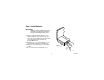
Step 7. Mount Thermostat Mounting Plate WALL ANCHORS (2) WIRES THROUGH WALL OPENING ❑ Position mounting plate on wall. Use level to make sure mounting plate is level. Use a pencil to mark the two mounting holes. ❑ Remove mounting plate from wall, and drill 3/16-inch holes in wall (if drywall) as marked. For firmer material such as plaster or wood, drill 7/32-inch holes. Gently tap anchors (provided) into drilled holes until flush with the wall.
❑ Level for appearance only; thermostat functions properly even when not level. ❑ Tighten mounting screws.
Step 8. Wire Thermostat Terminals NOTE: All wiring must comply with local codes and ordinances. If unsure about household wiring procedures, call your local heating/air conditioning contractor. METHOD TO INCREASE WIRE LENGTH ❑ Refer to the labels you placed on the terminal wires when you removed your old thermostat. Match the letter of your old thermostat wire with the terminal of the corresponding letter on the back of your new thermostat. (See wiring diagrams.
❑ Loosen the terminal screws and slip each wire beneath its matching terminal. See illustrations for wire insertion technique. ❑ Securely tighten terminals. ❑ Plug the hole in the wall with insulation to help prevent drafts from adversely affecting thermostat operation. Rc W Y G END OF WIRE VISIBLE HERE JUMPER (FACTORYINSTALLED). REMOVE IF 5-WIRE SYSTEM R 5/16 in.
2-WIRE HEAT-ONLY (JUMPER INTACT) 4-WIRE HEAT/COOL (JUMPER INTACT) A C A C B D B D W Y JUMPER G W Y G JUMPER Rc R HEATING RELAY OR VALVE COIL L1 (HOT) R HEATING RELAY OR VALVE COIL COOLING CONTACTOR COIL 1 L2 1 Rc POWER SUPPLY. PROVIDE DISCONNECT MEANS AND OVERLOAD PROTECTION AS REQUIRED. FAN RELAY M1709B L1 (HOT) L2 1 25 POWER SUPPLY. PROVIDE DISCONNECT MEANS AND OVERLOAD PROTECTION AS REQUIRED.
5-WIRE HEAT/COOL (JUMPER REMOVED) A C B D W Y 3-WIRE COOL-ONLY (JUMPER INTACT) A C B D G W Y G JUMPER R Rc R HEATING RELAY OR VALVE COIL FAN RELAY COOLING CONTACTOR COIL COOLING CONTACTOR COIL 1 FAN RELAY 1 L1 (HOT) L2 L2 L1 (HOT) 1 Rc L1 (HOT) L2 1 POWER SUPPLY. PROVIDE DISCONNECT MEANS AND OVERLOAD PROTECTION AS REQUIRED. M1711C 26 POWER SUPPLY. PROVIDE DISCONNECT MEANS AND OVERLOAD PROTECTION AS REQUIRED.
Step 9. Mount Thermostat NOTE: To remove thermostat from wall, first pull out at bottom of thermostat, then remove top. A. ENGAGE TABS AT TOP OF THERMOSTAT AND SUBBASE. B. PRESS LOWER EDGE OF CASE TO LATCH. C. SWING OPEN COVER TO CHECK OPERATION.
Step 10. Check Thermostat Operation After Programming and Installing Move the System switch to Heat and the Fan switch to Auto. Cool Off Heat M1703 Auto On M1705 Heating TEMP Press TEMP key until the setting is about 10°F (6°C) above room temperature. Heating should start and the fan should run after a short delay (immediately if fan operation switch is set to E position).
Cooling Move the System switch to Cool and the Fan switch to Auto. To avoid possible compressor damage, do not operate the cooling system when outdoor temperature is below 50°F (10°C). See compressor manufacturer instructions. Cool Off Heat M1704 Auto On M1705 IMPORTANT When cooling setting is changed, thermostat delays up to five minutes before turning on the air conditioner. This delay protects the compressor. TEMP Press TEMP key until setting is about 10°F (6°C) below room temperature.
Step 11. Set Fan and System Switches First set the Fan switch. Fan Auto: Normal setting for most Auto On homes. A single-speed fan will turn on automatically with the air conditioner or furnace. A two-speed fan usually runs on high with the air conditioner and on low with the furnace. Then set the System switch. Cool: The thermostat controls your air conditioning system. Off: Both the heating and air conditioning systems are off. Fan On: The fan runs continuously.
Troubleshooting Guide If... Then... Display does not come on. Set the System switch to Off. Remove batteries. Insert them backward for at least five seconds to reset the thermostat. Replace batteries correctly. Display should come on. Make sure batteries are fresh and installed correctly. You have reached the temperature setting limit. The setting range is 45°F to 88°F (7° to 31°C). Temperature display does not go lower than 45°F (7°C) or higher than 88°F (31°C) during programming.
If... Then... Heating does not come on. Check that the System switch is set to Heat. Make sure the heating setpoint is above the room temperature. Check the system fuse or circuit breaker and replace or reset, if necessary. Make sure the System switch is in the On position; set it to On if it is in the Off position. If temperature setting is higher than the current temperature and the display says HEAT, contact Honeywell Consumer Services at 1-800468-1502. Cooling does not come on.
If... Cooling does not come on (Continued). The house is too warm or too cool. SYSTEM ON indicator is lighted, but no heat is coming from the registers. Then... The thermostat has a built-in time delay on cooling. Allow five to ten minutes after changing the setting before the air conditioner starts. If temperature setting is lower than current temperature, and the display says COOL, move the System switch from Cool to Off for ten minutes. After ten minutes, return the switch to the Cool position.
Toll-free Customer Assistance For all questions concerning this thermostat, please read and follow the instructions. If additional assistance is needed, call Honeywell Consumer Services at 1-800-468-1502, Monday - Friday, 7:00 a.m. - 5:30 p.m. Central time. Before you call, please have the following information available—thermostat model number and date code, type of heating/cooling system (hot water, warm air, oil, gas, etc.), and number of wires connected to the thermostat.
Limited One-Year Warranty Honeywell warrants this product, excluding battery, to be free from defects in the workmanship or materials, under normal use and service, for a period of one (1) year from the date of purchase by the consumer. If, at any time during the warranty period, the product is defective or malfunctions, Honeywell shall repair or replace it (at Honeywell’s option) within a reasonable period of time.
THIS WARRANTY IS THE ONLY EXPRESS WARRANTY HONEYWELL MAKES ON THIS PRODUCT. THE DURATION OF ANY IMPLIED WARRANTIES, INCLUDING THE WARRANTIES OF MERCHANTABILITY AND FITNESS FOR A PARTICULAR PURPOSE, IS HEREBY LIMITED TO THE ONE YEAR DURATION OF THIS WARRANTY. Some states do not allow limitations on how long an implied warranty lasts, so the above limitation may not apply to you. This warranty gives you specific legal rights, and you may have other rights which vary from state to state.
TYPICAL ENERGY SAVINGS FOR REPRESENTATIVE CITIES IN THE U.S. AND CANADA Savings for Once-A-Day 10°F (5°C) decrease Savings for Twice-A-Day 10°F (5°C) decrease* Savings for 5°F (3°) summer increase Approximate percentage of energy cost savings 30% 28% 26% 24% 22% 20% 18% 16% 14% 12% 10% 8% 6% 4% 2% Minneapolis St. Paul Montreal Ottawa Toronto Edmonton Regina Winnipeg Calgary Moncton North Bay Quebec St.
69-1385
69-1385
Home and Building Control Honeywell Inc. Honeywell Plaza P.O. Box 524 Minneapolis, MN 55408-0524 69-1385 G.H. 6-00 Home and Building Control Honeywell Limited-Honeywell Limitée 155 Gordon Baker Road North York, Ontario M2H 3N7 Printed in U.S.A. on recycled paper containing at least 10% post-consumer paper fibers. www.honeywell.