Honeywell CT3650 PROGRAMMABLE THERMOSTAT OWNER’S GUIDE Seven Day Programmable Heat and/or Cool Low Voltage (20 to 30 Vac) Thermostat and Wallplate Model CT3650 Para pedir estas instrucciones en español, llame al 1-800-468-1502. Pour obtenir ce ode demploi en français, composer le 1-800-468-1502. Table of Contents Step 1. Prepare for Installation ................................................................................................................................... Step 2. Remove Old Thermostat .
Total comfort temperature management with Smart Response™ Technology. Congratulations! You made a smart choice by purchasing your new Honeywell thermostat; the smart thermostat that; • Keeps you comfortable by automatically calculating exactly when the furnace or air conditioning should go on to have the house at the desired comfort temperature by the time you wake up or return home.
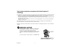
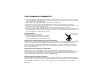
TIME DIGITAL DISPLAY /TIME SETS TIME FORWARD OR BACK RAISES TEMPERATURE SETTING SET CURRENT DAY/TIME LOWERS SETS CURRENT TIME AND DAY TEMPERATURE SETTING DISPLAYS CURRENT HEAT/COOL TEMPERATURE SETTING RUN PROGRAM RETURNS THERMOSTAT TO NORMAL OPERATING MODE Time Run Program HOLD TEMP Hold Temp SETS A HOLD TEMPERATURE SETTING AND ACTIVATES VACATION HOLD FEATURE Daylight Time Set Current Day/Time Return Sleep WAKE/LEAVE/RETURN/SLEEP: ENTERS PROGRAMMING MODE Heat/Cool Settings Day Copy PR
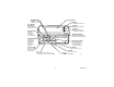
DISPLAYS EITHER CURRENT TIME OF DAY OR PROGRAM TIMES SHOWS THERMOSTAT IS IN THE SET DAY/TIME MODE SHOWS WHEN THERMOSTAT IS IN THE PROGRAMMING MODE SHOWS TEMPERATURE SETTING CHANGED FOR THIS PROGRAM PERIOD SHOWS VACATION HOLD DURATION SHOWS CURRENT DAY OR DAYS BEING PROGRAMMED SHOWS CURRENT PROGRAM PERIOD OR PERIOD BEING PROGRAMMED Set Program Set Day/Time Temporary Setting Hold for AM Em Ht Room Humid Aux Ht MonTueWedThuFriSatSun Days Outdoor WakeLeaveReturnSleep In Recovery Filter Repl Batt DST Fan
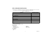
STEP 1. PREPARE FOR INSTALLATION ❑ Check Table 1, the compatibility chart, to make sure the thermostat is compatible with your system. If your system is not compatible, call Honeywell Customer Relations Center, toll-free, 1-800-468-1502. Table 1. Compatibility Chart.
STEP 2. REMOVE OLD THERMOSTAT ❑ Test your heating and cooling systems to make sure they work properly. If either system does not work, contact your local heating/air-conditioning dealer. To avoid compressor damage, do not operate the cooling system when outdoor temperature is below 50°F (10°C). ❑ Turn off power to the system at the furnace or the fuse/circuit breaker panel. ❑ Carefully unpack your new thermostat and wallplate. Save package of screws, instructions, and receipt.
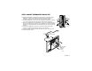
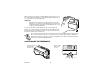
STEP 3. MOUNT THERMOSTAT WALLPLATE ❑ Separate the wallplate from the thermostat by placing your thumb or fingers between the bottom of the wallplate and the thermostat, and pulling the wallplate up and away from the thermostat. See illustration at right. ❑ Position the wallplate on the wall. Level the wallplate for appearance if desired. Use a pencil to mark the two mounting holes that best fit the application. ❑ Remove the wallplate from the wall. Drill two 3/16 in. holes in wall (if drywall) as shown.
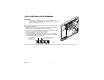
STEP 4. WIRE WALLPLATE TERMINALS IMPORTANT All wiring must comply with local codes and ordinances. If unsure about household wiring procedures, call your local heating/air-conditioning contractor. Y FOR WRAPAROUND INSERTION STRIP 7/16 IN. (11 MM). R W G Refer to the labels you placed on the wires when you removed the old thermostat (see illustration). ❑ Match the letter of your old thermostat wire with the corresponding terminal letter on your new thermostat. Refer to Table 2.
Table 2. Terminal Designations on Old and New Thermostats. Terminal on Old Thermostat Connect To Description R, RH , 4, V R Power Rc, Ra Rc Power for cooling W, W1, H W Heat a Y, Y1, M Y Cooling G, F G Fan O O Changeover in cool. (Single stage heat pump only). Bb Bb Changeover in heat. (Single stage heat pump only). C,X,B Do not connect. Transformer common W2, H2 Do not continue installation. Call 1-800-468-1502. Second stage heat. c Y2 c b Second stage cool.
When the batteries are running low, a REPL BAT message flashes for one to two months before the batteries run out completely. Replace the batteries as soon as possible once the message flashes. IMPORTANT Although the thermostat has a low battery indicator, replace the batteries once per year to prevent leakage and to prevent the thermostat and heating/cooling system from shutting down due to lack of battery power in the thermostat.
STEP 7. CUSTOMIZE YOUR THERMOSTAT Your Honeywell CT3650 thermostat comes preset to the most commonly used settings. The settings are: Gas or oil forced air furnace. Smart Response technology on. Temperature °F. 12-hour clock format. You can change any or all of these settings. IMPORTANT Always press the keys with your fingertip or a similar blunt tool. Sharp instruments like pens and pencil points can damage the keyboard. ❑ Press and hold down , , and , simultaneously until the screen shows.
❑ Press Time to move to next feature or Run Program to return to main display. Smart Response™ Technology (Feature Number 13) Smart Response technology options are: 0 = Smart Response technology on (preset). 1 = Smart Response technology off. M13343 To turn Smart Response technology on or off: ❑ Press once. ❑ Press Time NOTE: to move to next feature or Run Program to return to main display. See Smart Response technology (page 20) for information about this feature.
Factory Set Function (Feature Number 37) Do not change this setting. STEP 8. SET THE CLOCK M13346 Set Current Day and Time NOTE: On initial power-up, the screen flashes 1:00 pm until you press a key. ❑ Press Set Current Day/Time ❑ Press . until screen shows current day. Day ❑ Press Time or hour increments). ❑ Press Daylight Time ❑ Press Run Program until screen shows current time.
Return Sleep —The program period when you want the house at a comfortable temperature for activities before bedtime. (This is a higher temperature during the heating season and a lower temperature during the cooling season). —The program period you can set for an energy-saving temperature while you sleeping. (This is a lower temperature during the heating season and a higher temperature during the cooling season). Table 3 can be helpful when planning your schedule of time and temperature settings.
Program the First Day Start by programming the wake time and temperature for one day. ❑ Press and release ❑ Press ❑ Press time NOTE: ❑ Press Wake . until the desired day displays. (Mon, Tue, Wed, Thu, Fri, Sat, Sun) Day or until the desired time shows in the display. Program times are in 15 minute intervals. For example, 8:00, 8:15, 8:30. or until the desired wake temperature displays. The setpoint temperature range is 40°F to 90°F (4.
Copy a Day Your thermostat can copy program settings from one day to another. ❑ Press ❑ Press ❑ Press Wake , Copy Leave , Return Sleep or to enter programming mode. until the display shows the day you want to copy. Day . The display shows. Mon M13327 ❑ Press until the display shows the day you want to copy to. Day Mon Wed M13328 ❑ Press Copy to accept the change. ❑ Repeat these steps for each day you want to copy.
STEP 10. OPERATING YOUR THERMOSTAT Change Temperature Setting Until the Next Program Period (Temporary Change) ❑ Press NOTE: or until the screen shows the desired temperature setting. The temporary temperature setting is displayed for about 3 seconds and then the room temperature is displayed. Temporary appears in the display. The setting cancels when the next program period starts or when you press Run Program .
❑ Press time. NOTE: Daylight Time during the spring to set time forward one hour. DST is displayed when operating on daylight savings Pressing the Daylight Time key more than once in a five minute period scrolls you through various time option. For example, one hour earlier or later, with or without DST. Pressing Daylight Time six times in a five minute period returns you to your original setting. STEP 11. SET THE FAN AND SYSTEM KEY Set the Fan Key ❑ Fan On: The fan runs continuously.
IF YOU HAVE A PROBLEM Table 4. Solution Guide. If... Display does not appear. Then… Make sure the batteries are installed correctly. Make sure the thermostat is mounted and latched on the wall plate. Mount and latch the thermostat on the wallplate if it is not. • Make sure the temperature setpoints are: Temperature settings will not change (example; cannot set the heating higher 40 to 90°F (4.5 to 32°C) for heating. or the cooling lower). 45 to 99°F (7 to 37°C) for cooling.
Toll-Free Customer Assistance Please read and follow the provided instructions for this thermostat. For additional information, go to www.honeywell.com/yourhome or call the Honeywell Customer Relations Center at 1-800-468-1502. The Center hours are Monday through Friday, 7:00AM to 5:30PM Central Time. Before calling, please have the following information available: • Thermostat model number. (Located on back of thermostat). • Thermostat date code. (Located below model number).
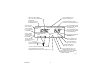
WIRING DIAGRAMS 4-WIRE HEAT/COOL (JUMPER INTACT) 2-WIRE HEAT-ONLY (JUMPER INTACT) THERMOSTAT B THERMOSTAT B RC O W Y RC O W Y R R G G HEATING RELAY OR VALVE COIL HEATING RELAY OR VALVE COIL COOLING CONTACTOR COIL FAN RELAY 1 1 1 POWER SUPPLY. PROVIDE DISCONNECT MEANS AND OVERLOAD PROTECTION AS REQUIRED. 1 POWER SUPPLY. PROVIDE DISCONNECT MEANS AND OVERLOAD PROTECTION AS REQUIRED.
5-WIRE HEAT/COOL (JUMPER REMOVED) 5-WIRE HEAT/COOL WITH DAMPER (JUMPER INTACT) THERMOSTAT B THERMOSTAT B RC O W Y RC O W Y HEATING RELAY OR VALVE COIL 1 FAN RELAY G R G R HEAT DAMPER COOLING CONTACTOR COIL 1 HEAT RELAY COOL DAMPER 1 POWER SUPPLY. PROVIDE DISCONNECT MEANS AND OVERLOAD M10619 PROTECTION AS REQUIRED. 1 COMPRESSOR CONTACTOR FAN RELAY 1 POWER SUPPLY. PROVIDE DISCONNECT MEANS AND OVERLOAD PROTECTION AS REQUIRED.
Limited One-Year Warranty Honeywell warrants this product, excluding battery, to be free from defects in the workmanship or materials, under normal use and service, for a period of one (1) year from the date of purchase by the consumer. If, at any time during the warranty period, the product is defective or malfunctions, Honeywell shall repair or replace it (at Honeywells option) within a reasonable period of time.
Home and Building Control Home and Building Control Honeywell 1985 Douglas Drive North Golden Valley, MN 55422 Honeywell Limited-Honeywell Limitée 35 Dynamic Drive Scarborough, Ontario M1V 4Z9 69-1285—2 J.H. Rev. 04-01 Printed in U.S.A. on recycled paper containing at least 10% post-consumer paper fibers. www.honeywell.