CT70 Heat Pump Thermostat Wiring Guide 1
HOW TO USE THIS GUIDE Before you disconnect the wires and remove your existing thermostat, be sure this new thermostat, see the CT70 wiring hookup diagram, will replace it and that you understand how you will reconnect the wiring. To do that, proceed as follows: Step 1 Find the manufacturer of your heat pump in the Table of Contents, and turn to the appropriate page.
TABLE OF CONTENTS How to Use This Guide ................................................. 3 Heat Pumps are Different .............................................. 6 Heat Pumps are Two Systems in One .......................... 7 Definitions of Terminal Functions ............................... 8,9 Heat Pump Manufacturers ..................................... 11-22 Amana....................................................................11 American Standard................................................
HEAT PUMPS ARE DIFFERENT Heat pump systems usually have a supplemental, Second Stage heating system that operates only when necessary. This heat pump thermostat is designed to minimize more expensive secondstage operation, indicated by the green AUX. HEAT light on your thermostat.
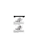
HEAT PUMPS ARE TWO SYSTEMS IN ONE MILD WEATHER INDOORS OUTDOORS AUXILIARY HEATING ELEMENT OFF OUTDOOR AIR INDOOR AIR HEAT TRANSFER M9069 In mild weather, virtually all of the demand for heat in buildings can be met by the heat pump compressor. This First Stage process of moving heat indoors is very economical. As the air becomes colder outside, the first stage may be unable to deliver enough heat to maintain the desired comfort level in the building.
DEFINITIONS OF TERMINAL FUNCTIONS Each terminal of the CT70 controls a different heat pump function. Here is a list of the possible heat pump functions: Function FIRST STG. HEAT: Definition When this terminal is activated, the heat pump is on and heating the living space. AUXILIARY HEAT: When this terminal is activated, the auxiliary heating source is on because the heat pump is unable to meet the heating demand of the living space. FIRST STG.
FAN: When this terminal is activated, the fan is on. With the fan switch in the auto position, the fan cycles on and off with the heat pump. With the fan switch in the ON position, the fan is on continuously. MULTIPLE AUX. HEAT LOADS: This terminal is activated when additional auxiliary heat loads are required. Because the CT70 only has provisions for one auxiliary heat load, these loads must be connected to the AUXILIARY HEAT terminal. OUTDOOR SENSOR: This terminal is not connected to the CT70.
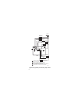
L1 (HOT) L2 1 CHANGEOVER RELAY (COOL) SYSTEM MONITOR AUX. HEAT RELAY FAN RELAY CHANGEOVER RELAY (HEAT) 4 X L 3 B W2 2 W1 E R G O Y1 EM. HEAT RELAY HEAT RELAY 1 COMPRESSOR CONTACTOR 1 POWER SUPPLY. PROVIDE DISCONNECT MEANS AND OVERLOAD PROTECTION AS REQUIRED. 2 REMOVE W1-Y1 JUMPER WHEN HEAT RELAY 1 IS USED. 3 WHEN L TERMINAL IS CONNECTED TO SYSTEM MONITOR, EM. HEAT. LED ALSO INDICATES COMPRESSOR MALFUNCTION. 4 X TERMINAL MUST BE CONNECTED FOR PROPER OPERATION.
AMANA Wiring terminal function Existing thermostat wiring COMMON X1 or C New thermostat wiring X 1 POWER R or RC or RH COMPRESSOR Y or Y1 Y1 1ST STG. HEAT W1 W1 AUX. HEAT W2 W2 FAN G G C/O VALVE HEAT B or W B C/O VALVE COOL O O EM. HEAT E E 2 R 3 SYSTEM MONITOR L ! Jumper these two terminals if both are present # This terminal must be connected to transformer common. $ Remove this factory-installed jumper for independent stage 1 heat and cool connection.
BARD/JANITROL/TAPPAN/WILLIAMSON Wiring terminal function Existing thermostat wiring COMMON C or X1 or X POWER RH or RC or R R COMPRESSOR Y Y1 1 New thermostat wiring X 2 1ST STG. HEAT W1 AUX. HEAT W2 W2 FAN G G B or W1 B O O SYSTEM MONITOR L L EM. HEAT E E MULTIPLE AUX. HEAT LOADS 3 W3 C/O VALVE HEAT C/O VALVE COOL 1 4 4 3 ! This terminal must be connected to transformer common. # Leave factory-installed jumper in place.
ARCOAIRE/SNYDER GENERAL/COMFORTMAKER Wiring terminal function COMMON Existing thermostat wiring X,X1 or C New thermostat wiring 1 X POWER R R COMPRESSOR Y Y1 1 2 1ST STG. HEAT W1 AUX. HEAT W2 or W1 W2 FAN G G C/O VALVE HEAT B C/O VALVE COOL O O SYSTEM MONITOR L or X L EM. HEAT E E ! This terminal must be connected to transformer common. # Leave factory-installed jumper in place.
B.D.P. (BRYANT-DAY/NIGHT-PAYNE) Wiring terminal function Existing thermostat wiring COMMON C1 or X1 or C New thermostat wiring 1 X POWER R R COMPRESSOR W1 or Y Y1 1 2 1ST STG. HEAT W1 AUX. HEAT W2 W2 FAN G G C/O VALVE HEAT B B C/O VALVE COOL Y1 or O O SYSTEM MONITOR L or F L E 3 EM. HEAT X or E MULTIPLE AUX. HEAT LOADS 3 W3 DEFROST P P ! This terminal must be connected to transformer common. # Leave factory-installed jumper in place.
CARRIER Wiring terminal function Existing thermostat wiring COMMON C POWER R R COMPRESSOR Y Y1 1 New thermostat wiring X 1 2 1ST STG. HEAT W1 AUX. HEAT W1 or W2 W2 FAN G G C/O VALVE HEAT B C/O VALVE COOL O O SYSTEM MONITOR F or L L EM. HEAT E E ! This terminal must be connected to transformer common. # Leave factory-installed jumper in place.
FRIEDRICH Wiring terminal function Existing thermostat wiring COMMON X or C or X1 New thermostat wiring 1 X POWER RH or RC R COMPRESSOR Y2 or Y Y1 1ST STG. HEAT W1 W1 AUX. HEAT W2 W2 FAN G G C/O VALVE HEAT B B C/O VALVE COOL O or Y1 SYSTEM MONITOR L L EM. HEAT E or X2 E 1 2 W3 or U O 3 ! This terminal must be connected to transformer common. # Leave factory-installed jumper in place. $ Tape off the end of the wire. Jumper is not required on this thermostat (CT70).
HEIL QUAKER/WHIRLPOOL/TEMPSTAR Wiring terminal function Existing thermostat wiring New thermostat wiring COMMON C or B X POWER R R COMPRESSOR Y Y1 2 1ST STG. HEAT W1 AUX. HEAT W W2 FAN G G C/O VALVE HEAT B B C/O VALVE COOL O O SYSTEM MONITOR EM. HEAT 1 L X E ! This terminal must be connected to transformer common. # Leave factory-installed jumper in place.
LENNOX Wiring terminal function Existing thermostat wiring New thermostat wiring COMMON Y or X X POWER 1ST STG. HEAT (COMP) BL or V/VR R or M 1ST STG. COOL O or Y FAN Y or F C/O VALVE HEAT W1 2 W2 G B BK or R SYSTEM MONITOR EM. HEAT R Y1 2ND STG. HEAT C/O VALVE COOL 1 O L E E ! This terminal must be connected to transformer common. # Leave factory-installed jumper in place.
RHEEM/RUUD Wiring terminal function Existing thermostat wiring COMMON X POWER R R COMPRESSOR Y Y1 1 New thermostat wiring X 1 2 1ST STG. HEAT W1 AUX. HEAT W2 W2 FAN G G C/O VALVE HEAT B B C/O VALVE COOL O O SYSTEM MONITOR L L EM. HEAT E E ! This terminal must be connected to transformer common. # Leave factory-installed jumper in place.
TRANE/AMERICAN STANDARD Wiring terminal function Existing thermostat wiring COMMON B POWER R 1ST STG. HEAT 1 New thermostat wiring X 1 R W1 2 Y Y1 AUX. HEAT W1 or W W2 FAN G G C/O VALVE HEAT B C/O VALVE COOL O O SYSTEM MONITOR F or L L OUTDOOR SENSOR T 3 OUTDOOR STAT W2 or X2 E ! This terminal must be connected to transformer common. # Leave factory-installed jumper in place. $ Tape off end. CT70 replaces outdoor reset with improved zero droop performance.
YORK/BORG WARNER/LUXAIRE (MONCRIEF, FRASER-JOHNSTON) Wiring terminal function Existing thermostat wiring New thermostat wiring COMMON X or B X POWER R R COMPRESSOR Y Y1 1 3 1ST STG. HEAT W1 AUX. HEAT W or W2 W2 FAN G G C/O VALVE HEAT H B C/O VALVE COOL O O SYSTEM MONITOR X or L EM. HEAT MULTIPLE AUX. HEAT LOADS 4 L 4 E E 4 W3 2 ! This terminal must be connected to transformer common. # Connect multiple second stage heating loads to W2 terminals.
YORK/BORG WARNER Wiring terminal function Existing thermostat wiring New thermostat wiring COMMON B or X2 X POWER R R 1ST STG. HEAT W1 W1 AUX. HEAT W2 W2 FAN G G 1ST STG. COOL Y1 Y1 C/O VALVE HEAT B C/O VALVE COOL O SYSTEM MONITOR L EM. HEAT E 1 2 E ! This terminal must be connected to transformer common. # Remove factory-installed jumper.
Automation and Control Solutions Honeywell International Inc. 1985 Douglas Drive North Golden Valley, MN 55422 69-0866—2 C.H. Rev. 01-95 www.honeywell.