CTS611 Heat Pump Thermostat Wiring Guide l Honeywell Home and Building Control Froneywell 1°C. 1985 Douglas Drive Norlh Golden Valley, Minncsotv 55422 ,H.-PrlniEdinT"lril"-FormNami,cr61~0817.
Before you disconnect the wires and remove your existing thermostat, make certain this new thermostat, see Figs. 1 and 2, will replace it and that you understand how you will reconnect the wiring. To do that, proceed as follows: Step 1 Find the manufacturer of your heat pump in the Table of Contents, and turn to the appropriate page.
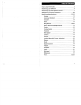
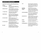
i How to Use This Guide ......... Heat Pumps are Different ....................................................... 6 American Standard ..... Arcoaire ..................... ...................... ...................... Carrier ............. Comfortmaker ..................... Friedrich ......... .................. ................. ......................................... 19 Luxaire (Moncrief, Fraser, Johnston) .......................... 22 Lennox ............... Rheem ...........................
Heat pump systems usually have a supplemental, "second stage" heating system that operates only when necessary. This heat pump thermostat is designed to minimize more expensive second-stage operation, indicated bv the areen AUX light on yo& swiching subbase. MILD WEATHER OUTDOORS INDOORS AUXILIARY HEATING ELEMENT OFF ..: INDOOR AIR 0 . With this thermostat, you will notice that your compressor operates continuously during the recovery period.
, Each terminal of the CT8611 controls a different heat pump function. Here is a listing of the possible heat pump functions: Function Definition 1" STAGE HEAT When this terminal is activated, the heat pump is on and providing heating to the living space. AUXILIARY HEAT When this terminal is activiated, the auxiliary heating source is on because the heat pump is unable to meet the heating demand of the living space.
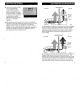
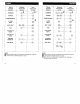
3T8611R CT8611R 0000000 0000000 00000 00000 0 , A ~ (HOT1 POWER SUPPLY. PROVIDE DISCONNECT MEANS AND OVERLOAD PROTECTION AS REOUIRED. Fig. I-Typical 10 Q; MP071 hookup of CT8611 with jumper intact. A POWER SUPPLY. PROVIDE DISCONNECT MEANS AN0 OVERLOAD PROTECTION AS REQUIRED. Fig. 2-Typical M8076 hookup of CT8611 with jumper removed.
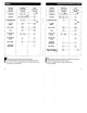
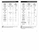
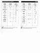
Wiring terminal function Existing thermostat wiring STG. HEAT AUX. HEAT FAN C/O VALVE HEAT C/O VALVE COOL EM. HEAT New thermostat wiring zm * * * * * a>., * @ (3 0 * (j+ 0 POWER COMPRESSOR STG. HEAT 1*T AUX. HEAT FAN CIO VALVE HEAT C/O VALVE COOL SYSTEM MONITOR Notes Jumper these two terminals if both are present. FA This terminal must be connected to transformer common. H Remove this factory-installed jumper for independent stage 1 heat and cool connection. * EM. HEAT VlULTlPLE AUX.