
Specification Sheet


51-52-03-36
Page 13
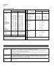
Dimensions
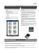
The controller is housed in a 4.5-inch (114 mm) deep, black plastic case with a dark gray elastomer bezel, that can be panel
mounted in a 1/4 DIN cutout. The plug-in chassis allows easy access to the controller board and its various option boards. All
power, input, and output wiring are connected to screw terminals on the rear panel. (See Figure 6.)
Max. panel thickness
19,1
.75
Panel
Cutout
92,0 + 0,8
-0,00
3,62 + 0,03
-0,00
92,0 + 0,8
-0,00
3,62 + 0,03
-0,00
mm
inches
17,9
0,70
113,1
4,45
90,6
3,57
108,6
4,28
9,0
0,35
Figure 5—UDC2500 Controller and Cutout Dimensions
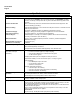
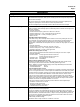
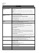
Wiring Diagram
L1
L2/N
4
5
6
7
8
9
20
21
25
26
27
19
10
11
12
13
14
15
16
18
17
Ethernet
SHIELD 14
RXD - 15
RXD + 16
TXD - 17
TXD + 18
R
T
D
Alarm #1
AC/DC
Line
Voltage
Earth Ground
Hot
Neutral
+
-
-
+
-
+
-
+
Input #1
Output #1
D
C
m
A
o
u
t
p
u
t
+
+
-
-
O
p
e
n
C
o
ll
e
c
t
o
r
S
o
lid
S
t
a
t
e
R
e
l
a
y
Input #2
RS485
16 SHIELD
17 D+ (B)
18 D - (A)
L
i
n
e
a
r
m
A
T
h
e
r
m
o
c
o
u
p
l
e
L
i
n
e
a
r
V
/
m
V
2
nd
Current Output
12 +
13 -
10 +
11 –
12 +
13 –
S
i
n
g
le
R
e
l
a
y
+
-
S
S
R
Output #2/
Alarm #2
O
p
e
n
C
o
ll
e
c
t
o
r
D
u
a
l
R
e
l
a
y
250
ohm
22
23
24
Digital Input #2Digital Input #1
2
1
S
i
n
g
l
e
R
e
l
a
y
L1
L2/N
4
5
6
7
8
9
20
21
25
26
27
19
10
11
12
13
14
15
16
18
17
Ethernet
SHIELD 14
RXD - 15
RXD + 16
TXD - 17
TXD + 18
R
T
D
Alarm #1
AC/DC
Line
Voltage
Earth Ground
Hot
Neutral
+
-
-
+
-
+
-
+
Input #1
Output #1
D
C
m
A
o
u
t
p
u
t
+
+
-
-
O
p
e
n
C
o
ll
e
c
t
o
r
S
o
lid
S
t
a
t
e
R
e
l
a
y
Input #2
RS485
16 SHIELD
17 D+ (B)
18 D - (A)
L
i
n
e
a
r
m
A
T
h
e
r
m
o
c
o
u
p
l
e
L
i
n
e
a
r
V
/
m
V
2
nd
Current Output
12 +
13 -
10 +
11 –
12 +
13 –
S
i
n
g
le
R
e
l
a
y
+
-
S
S
R
Output #2/
Alarm #2
O
p
e
n
C
o
ll
e
c
t
o
r
D
u
a
l
R
e
l
a
y
250
ohm
250
ohm
22
23
24
22
23
24
High Level Only
L1
L2/N
4
5
6
7
8
9
20
21
25
26
27
19
10
11
12
13
14
15
16
18
17
Ethernet
SHIELD 14
RXD - 15
RXD + 16
TXD - 17
TXD + 18
R
T
D
Alarm #1
AC/DC
Line
Voltage
Earth Ground
Hot
Neutral
+
-
-
+
-
+
-
+
Input #1
Output #1
D
C
m
A
o
u
t
p
u
t
+
+
-
-
O
p
e
n
C
o
ll
e
c
t
o
r
S
o
lid
S
t
a
t
e
R
e
l
a
y
Input #2
RS485
16 SHIELD
17 D+ (B)
18 D - (A)
L
i
n
e
a
r
m
A
T
h
e
r
m
o
c
o
u
p
l
e
L
i
n
e
a
r
V
/
m
V
2
nd
Current Output
12 +
13 -
10 +
11 –
12 +
13 –
S
i
n
g
le
R
e
l
a
y
+
-
S
S
R
Output #2/
Alarm #2
O
p
e
n
C
o
ll
e
c
t
o
r
D
u
a
l
R
e
l
a
y
250
ohm
250
ohm
22
23
24
22
23
24
Digital Input #2Digital Input #1
2
1
S
i
n
g
l
e
R
e
l
a
y
L1
L2/N
4
5
6
7
8
9
20
21
25
26
27
19
10
11
12
13
14
15
16
18
17
Ethernet
SHIELD 14
RXD - 15
RXD + 16
TXD - 17
TXD + 18
R
T
D
Alarm #1
AC/DC
Line
Voltage
Earth Ground
Hot
Neutral
+
-
-
+
-
+
-
+
Input #1
Output #1
D
C
m
A
o
u
t
p
u
t
+
+
-
-
O
p
e
n
C
o
ll
e
c
t
o
r
S
o
lid
S
t
a
t
e
R
e
l
a
y
Input #2
RS485
16 SHIELD
17 D+ (B)
18 D - (A)
L
i
n
e
a
r
m
A
T
h
e
r
m
o
c
o
u
p
l
e
L
i
n
e
a
r
V
/
m
V
2
nd
Current Output
12 +
13 -
10 +
11 –
12 +
13 –
S
i
n
g
le
R
e
l
a
y
+
-
S
S
R
Output #2/
Alarm #2
O
p
e
n
C
o
ll
e
c
t
o
r
D
u
a
l
R
e
l
a
y
250
ohm
250
ohm
22
23
24
22
23
24
High Level Only
Figure 6—External Wiring Diagram