
Specification Sheet


51-52-03-36
Page 4
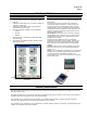
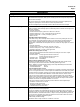
Operator Interface
See Display Indicators below
See Keys and Functions below
Figure 2—Operator Interface (all display indicators shown)
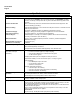
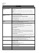
Display Indicators
Upper display with 4 larger digits shows Process
Variable value (normal operation) or parameter
value (configuration). Selectable decimal position.
Indicates either degrees Fahrenheit or Centigrade.
Lower display with 6 smaller characters shows
operating parameters and values (normal
operation) or functions and parameters
(configuration). Selectable decimal position.
Indicates either Manual or Auto mode.
Indicates Alarm 1 and/or Alarm 2 conditions exist.
Indicates either Remote or Local Setpoint2.
Indicates Control Relay 1 and/or 2 on.
Keys and Functions
Selects functions within each configuration
group.
Selects Manual or Auto mode. Resets the latching
limit Controller relay. In Set Up mode, used to
restore original value or selection.
Scrolls through the configuration groups.
Hold key down to cycle through configured setpoints.
Returns Controller to normal display from
Set Up mode. Toggles various operating
parameters for display.
Enables Run/Hold of the SP Ramp or Program plus
Timer start.
Increases setpoint or output value.
Increases the configuration values or
changes functions in Configuration mode
groups.
Decreases setpoint or output value. Decreases the
configuration values or changes functions in
Configuration mode groups.
Infrared transceiver
NEMA4X and IP66 screw attachment (each corner)