
DCP552 Mark II Digital Control Programmer User's Manual

7-35
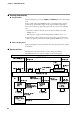
● C99 (PV1 zener barrier adjustment)
● C100 (PV2 zener barrier adjustment)
The adjustment described below must be performed when a zener barrier is
used.
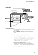
(1) Turn off the DCP552. When installation and wiring is completed, short-
circuit A and B on the resistance temperature detector.
(2) Turn on the DCP552 and set setup data C98 to 241.
(3) Display setup data C99 and C100.
(4) Press the ENTER key to display the difference in resistance (A-B) between
zener barriers connected to wire A and wire B.
(5) Press the ENTER key to store the difference in resistance values (A-B) in
the DCP552.
(6) Press the DISP key to return to the normal display mode.
(7) urn off the DCP552 and disconnect the wire between A and B.
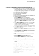
Handing Precautions
• Adjust the resistance in the zener barriers connected to wire A and B to
20Ω or less. Adjustment is not possible if the resistance is higher than
20Ω.
•This adjustment is not required for inputs other than resistance
temperature detectors or when zener barriers are not to be used.
• When a zener barrier has been adjusted, compensation is performed for
this zener barrier. When resistance temperature detector inputs not
employing zener barriers are to be used, perform the above adjustment
without the zener barriers.
Chapter 7. PARAMETER SETUP