Dolphin® Power Tools With Windows Mobile® 6 for the: Dolphin 7600 Mobile Computer Dolphin 9900 Mobile Computer User’s Guide
Disclaimer Honeywell International Inc. (“Honeywell”) reserves the right to make changes in specifications and other information contained in this document without prior notice, and the reader should in all cases consult Honeywell to determine whether any such changes have been made. The information in this publication does not represent a commitment on the part of Honeywell.
Table of Contents Chapter 1 - Accessing and Upgrading Power Tools Dolphin Power Tools Overview ...................................................................................... 1-1 Software Requirements ................................................................................................. 1-2 Power Tools Main Window ............................................................................................ 1-2 Additional Dolphin Power Tools ..................................................
Autorun ...........................................................................................................................4-1 Autorun.exm File.......................................................................................................4-1 Start Options.............................................................................................................4-4 AutoInstall.....................................................................................................................
Exporting Specific Registry Settings...............................................................................8-5 Other Export Options ................................................................................................8-5 Backing Up the Registry .................................................................................................8-6 Restoring the Registry ..............................................................................................8-6 RegBackup.exm ............
vi Rev A 8/6/08 Dolphin® Power Tools User’s Guide
1 Accessing and Upgrading Power Tools Dolphin Power Tools Overview Dolphin Power Tools are installed in every Dolphin terminal. Different versions of Power Tools apply to different Dolphin terminals depending on their model or operating system. Power Tool Windows Mobile 5/6 Windows Mobile 2003 Second Edition Windows CE 5.0 6: 7600 (GSM)/9900 5.
Software Requirements Dolphin Terminals Dolphin Power Tools are designed to work with Windows Mobile® 6 Desktop The Power Tools installer and the workstation version of EZConfig Editor are designed to work with the following operating systems: • • • • • • Microsoft® Windows® XP Microsoft® Windows® 2000 Microsoft® Windows® NT Microsoft® Windows® Vista Microsoft® .NET Framework 2.0 Microsoft® ActiveSync® (version 4.
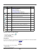
Icon Name Description Page Network Utilities Opens a window that displays the Network utilities: • IP Config (see page 9-2) • Ping (see page 9-4) • Route (see page 9-6) • WiFi Status (see page 9-10) • Backup Radio Settings (see page 9-12) • Restore Radio Settings (see page 9-12) 9-1 RASMan Establishes a remote access service (RAS) connection. 6-10 Reboot Performs a warm or cold boot from the touch screen, as opposed to the keyboard commands. 6-13 RegBackup Backs up the registry.
• List View • Detail View (This view displays a description of the Power Tool in a column to the right of the name.) Additional Dolphin Power Tools These Power Tools are in the Dolphin terminal but do not appear on the Power Tools main window. Name Function Storage Location Access Location Page AutoInstall Installs CAB files after a hard reset. \IPSM \IPSM\AutoInstall 4-8 AutoRun Programs which applications launch at startup. \IPSM \IPSM 4-1 BTPrint Prints to a Bluetooth device.
Upgrading Power Tools Dolphin Power Tools come loaded in every Dolphin terminal and are included in system upgrades. Acquiring Upgrades Upgrades are available from Customer Support (see page 13-1) or www.honeywell.com/aidc. Installing an Upgrade to the Workstation Power Tools upgrades come in the form of an upgrade executable that installs upgrade files to the workstation. Transfer the appropriate upgrade files to the Dolphin terminal.
4. Click Next. 5. Accept or change the installation location then click Next.
6. Click Install and the programs begin installing. 7. The following screen appears when the programs have finished installing: 8. Click Finish.
Folder on the Workstation After installation on the workstation is complete, the upgrade files are stored on the workstation at C:\Program Files\Honeywell\Power Tools and Demos for WM 6.0. Note: If a Honeywell folder does not already exist in the Program Files folder, the installation creates one. Device Image A ghost image of the IPSM upgrade. The contents of this folder should replace the contents of the \IPSM folder on the Dolphin terminal.
9. When all the files are pasted, cold boot the terminal. 10. The Power Tools upgrade installs during startup.
1 - 10 Rev A 8/6/08 Dolphin® Power Tools User’s Guide
2 EZConfig Overview EZConfig is a suite of products that configures Dolphin terminals quickly and efficiently. With the tools in the EZConfig suite, you can package data on the workstation, then deploy and unpackage that data on the Dolphin terminal. Components There are two main components to EZConfig: EZConfig Editor and EZConfig Client. EZConfig Editor Edits and creates configuration and registry documents in the EXM file format for Dolphin terminals.
EZConfig Editor EZConfig Editor creates, edits, and manages EXM files for Dolphin terminals. There is an EZConfig Editor on the workstation and an EZConfig Editor on the terminal. In the workstation editor, EXM files are edited, saved, then transferred to the terminal. In the terminal editor, EXM files are edited and saved right on the terminal; see EZConfig Editor on the Terminal (page 2-30).
Use these files as templates to create new EXM files. Opening EZConfig Editor on the Workstation After you complete installation, EZConfig Editor is available on the workstation from the Start menu. Click Start > Programs > Honeywell > EZConfig Editor > EZConfig Editor. Menu Toolbar Menu and Toolbar Options The menu and toolbar at the top of the window contains many options. File Menu Menu Item New Open Open from Device Description Creates a new document.
File Menu Menu Item Description Save Saves the open file to the location you select on the workstation. This option is disabled for new and imported files; use Save As instead. Save As Saves the open file with a new name to the location you select on the workstation. Save to Device As Saves an open file to the terminal; see Saving to the Device on page 2-14. Note: Requires an ActiveSync connection between the workstation and the terminal.
Tools Menu Menu Item Description Simplify Document Note: You cannot undo this action! Simplifies the EXM file, which makes it smaller. Simplifying permanently removes • Disabled sections and keys • Descriptions • Bar code settings When you create a bar code, you can simplify the file embedded in the bar code without affecting the open EXM file. This reduces the size of the bar code package yet keeps the disabled sections, descriptions, and bar code settings in the open EXM file for future reference.
Opening EXM Files EZConfig Editor opens EXM files stored on the workstation or the terminal (if an ActiveSync connection is established). Opening EXM Files on the Workstation Click File > Open or the Open toolbar button and select the EXM file. When you select a known MNU or INI file, EZConfig Editor prompts you to convert the file. When you select Yes, EZConfig Editor imports the file and converts it to the EXM file format. Then, you can click File > Save As to save the file with the EXM extension.
Working with Open EXM Files Whether you open an EXM or INI file, EZConfig Editor displays the content in four different sections of the window. Displays the file name. If the file is on the terminal, the title bar displays the remote path. Displays the root node and sections. Select a section and the details appear in the other portions of the window. The folders appear in different colors to indicate their status. Displays the keys in the selected section. Text that appears in blue can be edited.
Edit Menu Options Select a section click Edit to see the available options. Menu Item Description Rename Activates the section name so that you can rename the section. Note: You cannot modify the name if the section is locked; see Section Locks (page 2-10). Cut Cuts a selected section. Copy Copies a selected section. Paste Pastes the section that was just cut or copied at the same level as the selected section.
Menu Item Description Insert Section This menu item inserts a new section. You can also press the Insert key (INS). Append Child Section This menu item adds a new child section to a selected section. The new child section is inserted below the previous section. Modifying Section Names To change a section name, double-click on the folder and type in the new name or select Rename on the Edit menu. Type in the new name and press ENTER.
Section Locks There are different types of locks on sections. The status bar indicates what type of lock is applied to a selected section. Lock Type Status Bar Indicator Description Effect Name Lock The section name is locked. • Section Name and Description cannot be modified. Key Lock All keys are locked. • Key Names and Descriptions cannot be modified. • Keys cannot be added, moved, or deleted within the section. Subsection Lock All immediate subsections are locked.
To change section-level merge modes, select a section and right click. The folder colors change immediately after selection.
Working with Keys Keys have a Name, a Description, and a Value and reside inside sections. For specific key values, consult the chapters of this user’s guide that describe the EXM file you’re attempting to edit. Edit Menu Options Select a key and right-click or click Edit to see the available options. The same options appear on both menus. Menu Item Description Rename Activates the key name so that you can rename the key. Rename is disabled if the key is locked or disabled; see Key Types (page 2-14).
Menu Item Description Disable Disables keys. Disabled keys have key values in black. Enabled keys have key values in blue. The terminal does not read disabled keys and disabled keys are removed if the file is simplified; see Simplify Document (page 2-5). Because many key values are 1 for enable and 0 for disable, remember that disabling a key means that the terminal behaves as if the key is not there when reading the file, NOT that the key’s value is set to disabled.
Key Types When a key is selected, its properties display in the Status bar. Lock Type Status Bar Indicator Description Effect Keys are locked by the section. • Name and Description cannot be modified. • Keys cannot be added, moved, or deleted within the section. The key name is locked individually. • Name and Description cannot be modified. • These keys can be moved. Read Only Read-only keys cannot be modified in any way. They appear in red. • Name, Description, and Value cannot be modified.
Creating New Configuration Documents To create new EXM files that are configuration documents, you can open an existing EXM file and save it with a new name or create an EXM file from scratch. 1. Click File > New > Configuration Document. The root node is created and appears as the top level section. All sections must be at least one level down from the root node. The name of the root node is always the same as the filename. The terminal reads root node first.
Associating Applications The Properties function associates an EXM file with an application on the terminal. The associated application launches after EZConfig Client decodes the bar code containing the EXM file. For more information, see Creating Bar Codes on page 2-21. While the EXM file is open, click File > Properties or the Document Properties toolbar button . Field Description Path Enter the location of the EXE on the terminal.
Registry Documents EZConfig Editor creates registry documents in the EXM file format and also opens existing REG files and converts them to the EXM file format. EZConfig Editor cannot save registry documents in the REG file format.
Creating Registry Documents 1. In EZConfig Editor, click File > New > Registry Document. 2. The new document contains the three top-level sections in a registry. These sections are locked and cannot be changed. You can add subsections to each section and then add keys to those subsections. Click File > Save As. 3. Choose the name and location and click Save. You cannot save the document as a .reg file; you must save it as an EXM file. 4.
Adding Registry Keys To add a key, select a section, and right-click in the key area of the EZConfig Editor window. Field Description Name Enter the key’s name. Registry Value Type Select the registry type from the drop down list. This value appears in the Type column. Value Enter the key’s value. Desc Enter a description for the key; descriptions appear in the lower half of the EZConfig Editor window when the key is selected.
If you do not want to store the registry EXM file on the terminal after updating the registry, select the Temporary (page 2-25) option on the Bar Codes Tab (page 2-22). Persistent Registry Documents If you want to update the registry during every cold boot, create a registry document in the EXM format, save it to the terminal in the \IPSM\AutoInstall folder, and cold boot. The registry settings in the EXM file will load during startup.
Creating Bar Codes EZConfig Editor embeds EXM files in bar codes. The EZConfig Client on the terminal decodes the bar code and deploys the data. Using bar codes quickly and easily configures Dolphin terminals without an IrDA, ActiveSync, or network connection to a workstation. Document Types EZConfig Editor produces two kinds of EXM files: configuration documents and registry documents. Both can be embedded in bar codes and processed by EZConfig Client on the terminal.
Bar Code Sheet EZConfig Editor produces a bar code sheet that contains the generated bar codes. Bar code sheets can be printed from a laser printer, copied to the clipboard, and saved as an HTML file; see Printing and Saving Options on page 2-26. In addition, individual bar codes can be saved as TIF or PNG graphic files that can then be emailed and printed; see Bar Codes Tab on page 2-22.
Field/Option Description Remote Path Type in the location and filename where the EXM file should be deployed on the terminal. For instance, \ipsm\deviceconfig.exm Tap the browse button to navigate to the location on the terminal. Your ActiveSync connection must be active. Full Contents Includes the full content of the EXM file in the bar code, without simplifying.
Advanced Tab The Options tab contains settings that tell EZConfig Client how to process the EXM file on the terminal. Field Description Bar Code Options–This section determines some of the basic bar code parameters. Max Barcode Size Set the maximum amount of data (in bytes) one bar code can contain. The lower the number of bytes, the smaller the bar code. • On the Bar Codes tab, bar code size appears in the Display field (see page 2-22).
Field Description Merge each section… Deploys information according to the section-level merge mode settings; see SectionLevel Merge Modes on page 2-10. If already exists, deploy: • Always–Select to always use the section-level merge mode settings. • Only if newer–Select to use the section-level merge mode settings only if the sections are newer than the existing file. (Default selection) Temporary Deploys the EXM file temporarily.
Information at the Bottom of Tab Windows Field Description Package Size Displays the total size of the bar code package. This number changes with simplifying. Compression On Notifies you that compression and encryption are both on. Compression and encryption are always on by default. EZConfig Editor uses 128-bit encryption automatically. Encryption On Bar Codes Displays the total number of bar codes generated. This number changes as you move the slider on the Bar Codes tab.
Field/Option Description Save Saves the bar code sheet as an HTML file. Preview Click to see a print preview. Click Print on this window to print your bar codes.
Converting Known INI and MNU Files EZConfig Editor contains a batch conversion tool that converts known INI files on the terminal to the new EXM file format. EZConfig Editor pulls INI files from the \IPSM folder of a remote device, converts them to the EXM file format, and saves both original INI files and the converted EXM files in folders created on the workstation. You don’t lose your original INI files in the conversion.
4. 5. C:\Program Files\Honeywell\Power Tools and Demos for WM 6.0\Device Image\Converted Files\Upgrade X. The X increases by one each time you run a batch conversion. When you click OK, the conversion runs. EZConfig Editor creates two folders inside the Upgrade X folder: Converted EXMs and Original INIs. Note: 6. An Upgrade X folder with these two subfolders is created every time you run a conversion. Upgrades do not save over each other. Check each converted EXM file in EZConfig Editor.
EZConfig Editor on the Terminal EZConfig Editor on the terminal edits and creates EXM files in the terminal and contains the same basic functionality as the editor on the workstation. Accessing EZConfig Editor Tap Start > Power Tools > EZConfig Utilities . The EZConfig Utilities window provides access to both the EZConfig Editor and the EZConfig Client (see page 2-34) as well as the EXM files on the terminal. Opening EXM Files • Tap directly on an EXM file to open it in EZConfig Editor.
Available Menus The menus in the Command bar contain the same items as the menus in the EZConfig Editor on the workstation. File Menu For details, see File Menu on page 2-3. Note: The one difference in the file menus is that you cannot generate bar codes from EXM files on the terminal. Edit Menu The Edit menu pops up when you tap and hold on a section or key. For details, see Edit Menu on page 2-4. View Menu This menu enables you to view the locked icon over locked section folders.
4. Tap OK to save changes. (You can also press the ENTER key.) Tap Cancel to close the window without changes. Moving Sections You cannot drag and drop to move sections in the tree. Use the Cut, Copy, Paste, and Paste as Child items on the Edit menu to move sections. Note: The Paste function pastes sections at the same level they were cut by default. Editing Keys Modifying Text To edit a key’s name, value, or description, you have three options: 1.
Launching Associated Applications The Tools menu contains an item named Launch Associated App. Launch Associated App is enabled only when there is an application associated with the EXM file. Selecting this item automatically saves the open EXM file and launches the associated application while the EXM file remains open. To see the associated application, tap File > Properties. The Path field contains the launch location of the application.
EZConfig Client EZConfig Client decodes bar codes created in EZConfig Editor and deploys the data in the terminal. In addition, if the EXM file in the bar code is associated with an application, EZConfig Client launches that application, which then processes the decoded data. EZConfig Client decodes bar codes with 40-bit and 128-bit encryption. Storage Location The EZConfig Client executable is stored in the \IPSM folder.
If there is only one bar code in the package, EZConfig Client deploys the package. If there is more than one bar code in the package, EZConfig Client decodes the bar code, records that one bar code has been read, and waits for the next scan. 5. Scan all the bar codes in the package. Bar codes can be scanned in any order. 6. When all bar codes in the package have been scanned, the EZConfig client deploys the data.
Note: DeviceConfig.exm must be associated with DeviceConfig.exe to be processed on the terminal appropriately. After decoding the bar code, EZConfig Client deploys the data to DeviceConfig.exe, which applies the settings to the terminal. Registry Documents Registry documents are always associated with EZConfig Client. The Execute option (Execute, page 2-16) determines whether the registry is updated or not.
Launching EZConfig Client with a HotKey Pressing ALT + SCAN launches EZConfig Client from any application window after you activate the HotKeys Power Tool; see HotKeys on page 6-5. ScanWedge Bar code decoding in EZConfig Client is compatible with ScanWedge. You can set ScanWedge to pass bar code information to EZConfig Client for further processing. For details, see Accept EZConfig on page 5-4. Command Line Arguments /%filename /q /s /o /e /u Executes the EXM file; this is the default entry.
2 - 38 Rev A 8/6/08 Dolphin® Power Tools User’s Guide
3 DeviceConfig Overview DeviceConfig consists of the DeviceConfig.exe and the DeviceConfig.exm file located in the \IPSM folder. DeviceConfig.exe looks for and applies the settings in the DeviceConfig.exm file. DeviceConfig.exm File The DeviceConfig.exm file contains terminal configuration settings. Because this file is stored in the \IPSM folder, its configuration settings persist through cold boots and should be considered system defaults.
DeviceConfig.exm Sections and Keys The sections and keys in the DeviceConfig.exm file are locked, which means that you can change values but not names or descriptions. Section Name Description See Page Connections Configures communication parameters. There are child sections that configure the IrDA port, the on-board radios, and the ActiveSync connection. 3-2 System Configures basic system settings. 3-9 Applications Configures software applications.
WiFi Section The keys in the WiFi section control the settings of the WLAN radio. Key Description Default Value Available Values DriverName Specifies the name of the radio driver. This string must match the name of the driver for the current device. N/A X=A value in the drop-down list; radio driver names are terminal-specific. Different Dolphins have different radio drivers. TCPIP Section The keys in the TCPIP section determine how the radio handles IP addresses.
Security Section The Security section has no keys and one child section named “Supplicant,” which contains several profile subsections. Supplicant Section The Supplicant section consists of a number of child sections. The default child section is named Profile1 and contains all the keys necessary to create a configuration profile for the WLAN radio. To create multiple radio configurations, copy the Profile1 section and paste it at the root level of the Supplicant section.
Profile Subsections Each Profile subsection contains the keys that configure the radio connection from the terminal to the network. Key Description Default Value Available Values EAP Method Available EAP methods for IEEE 802.1X and WPA(2)-Enterprise (EAP) association modes. N/A • • • • • • • • • • • • PSK Enter the private share key for the WEP association mode. N/A User-defined Identity This is the 802.1X identity supplied to the authenticator.
Profile Subsections Each Profile subsection contains the keys that configure the radio connection from the terminal to the network. Key Description Default Value Available Values Private Key Private keys are used with certain types of EAP authentication. N/A Enter the address on the Dolphin terminal of the private key. The private key must be located on the Dolphin terminal! Priv Key Password Private keys can be locked by passwords. N/A Enter the password that unlocks the private key.
Bluetooth Section The keys in this section enable the Bluetooth radio and configure a Bluetooth printer as a Favorite. If there is no Bluetooth radio installed in the terminal, disable this section. Key Description Default Value Available Values Enable Enable and disable the Bluetooth radio. This is the top level of the tree; printer settings are in a child section.
GSM Section If there is no GSM radio installed in the terminal, disable this section. Key Description Default Value Available Value Enable Enables and disables the GSM radio. 0 0=Disable 1=Enable; when enabled, the WLAN radio turns off automatically. APN Enter the Access Point Name (APN) for the GPRS network. Empty APN value IPAddress Enter the IP Address. Empty Empty=GSM uses DHCP (serverassigned IP address) X=IP address Protocol Enter the protocol to use.
System Section The System section contains child sections that configure various system settings. For specifics on each sections and their keys, refer to the Description sections in the DeviceConfig.exm file itself. About Section The About section sets a unique device name and description for the terminal. By default, this section is enabled and applied to the terminal after each cold boot. Key Name Description Default Value Available Values DeviceName Sets the name of the device.
RAM Section The RAM section allows you to provision RAM memory on Windows Mobile 6.0-based terminals. Key Description Default Value Available Values Split This is the RAM split percentage; the percentage that will be allocated to the filesystem. 50 Min=0 Max=100 See Split Restrictions on page 3-10. Prompt Determines whether the system prompts you before the memory is reallocated. 1 0=Disabled; you will not be prompted. DeviceConfig’s settings are applied automatically.
MobiConrol Section If the terminal includes the MobiControl Bootstrap Agent (/IPSM/MCBootstrapAgent.exe), then DeviceConfig can be used to configure the terminal to connect to a MobiControl Server and download the appropriate agent to the device. This section is disabled by default and should only be enabled when configuring the device to connect to the MobiControl Server for the first time. The root level of the MobiControl section contains the main ConfigPath. By default, this is “\IPSM\MCBootstap.ini.
Command Line Arguments /q Quits the program; this command line in the Args field of the Associated Application window stops the confirmation message from appearing after DeviceConfig.exe finishes processing. /boot Reboots DeviceConfig.
Launching DeviceConfig.exe Manually DeviceConfig.exe does launch automatically after each cold boot. However, if you make changes to the DeviceConfig.exm file that you want applied in the terminal immediately, manually launch DeviceConfig.exe. 1. Tap Start > Power Tools > EZConfig Utilities > DeviceConfig.exm. 2. Tap Tools > Launch Associated App. 3. The settings in the DeviceConfig.exm file are saved and applied to the terminal configuration by DeviceConfig.exe. 4.
3 - 14 Rev A 8/6/08 Dolphin® Power Tools User’s Guide
4 Autorun and AutoInstall Overview Startup is the launch sequence when a Dolphin terminal is booted. There are two startup Power Tools: 1. Autorun (see page 4-1) 2. AutoInstall (see page 4-8) Autorun Autorun specifies the software applications to launch after each hard reset. Autorun is located in the \IPSM folder and consists of an Autorun.exe that is programmed by the Autorun.exm File (page 4-1). During startup, after a soft or hard reset, the operating system looks for and launches \IPSM\Autorun.
When processing files, the terminal behaves as though disabled sections are not there and moves on to the next enabled section. Settings Section Keys Note: This section and most of its keys are locked, which means that you can change the value but not the name or description. Key Function Default Available Values Version Stores the EXM file version.
Keys in Each Programs’ Subsection Each Programs’ subsection contains or can contain the following keys: Key Function Required Keys—These keys must be present in each Program subsection. Program Specifies the command line to execute. This is the location of the program’s executable. If you want a Power Tool to launch at startup, enter the location of that tool’s EXE here. Args Specifies the command line arguments to execute at startup.
6. Save the file and transport it to the terminal. Copying a File If you want to copy a file and move it to another location, use AutoInstall and the /copy command line argument. For details, see Command Line Arguments on page 4-10. Sample Autorun Configuration File A sample Autorun.exm file installs on the workstation to C:\Program Files\Honeywell\Power Tools and Demos for WM 6.0\EZConfig EXM Files. For more information, see Sample EXM Files on page 2-2.
Start Options Start Options define the required system parameters for a software application to launch. The following values can be entered for the StartOption key, wherever it appears: Option Name The program launches if … RFON The RF radio is Enabled. GSMON The GSM radio is enabled. BTON The Bluetooth radio is enabled. RFGSMBTOFF The RF, GSM, & Bluetooth radios are disabled. 29KEY The terminal has a 29-key keyboard. 35KEY The terminal has a 35-key keyboard.
Start Options Start Options define the required system parameters for a software application to launch. The following values can be entered for the StartOption key, wherever it appears: Option Name The program launches if … 7300 It’s a Dolphin 7300 terminal. 7400 It’s a Dolphin 7400 terminal. 7450 It’s a Dolphin 7450 terminal. 74XX It’s any Dolphin terminal beginning with “74”. 7600 It’s a Dolphin 7600 terminal. 76XX It’s any Dolphin terminal beginning with “76”.
Applying Startup Options to the Autorun Configuration File For each category, Autorun validates each startup option specified in the StartOption key. If no specified option is valid in a category, Autorun does not execute the program. If at least one of the specified options is valid in each category evaluated, the program is executed. To always execute a program, specify no options in the StartOption key.
AutoInstall AutoInstall consists of an AutoInstall.exe that, when launched, installs the cab files in the AutoInstall folder. The AutoInstall folder is where you store cab files for software applications if you want them to persist through hard resets. The AutoInstall program runs according to the settings in the AutoInstall.exm file. Program Install Locations When triggered by a hard reset, the CAB file installs the applications to the directories established in the CAB file.
AutoInstall.exm The AutoInstall.exm file controls the behavior and appearance of the AutoInstall window and install process. AutoInstall window Key Function Default Value Available Values Version This is the current version of the AutoInstall.exm file. This key is read-only and cannot be modified. 3 N/A Debug Enable and disables logging of debug information to \IPSM\AUTOINSTALL.LOG. 0 0=Disabled 1=Enabled Cancel Enable and disables the Cancel button on the AutoInstall window.
Key Function Default Value Available Values Password Establishes a password required to halt AutoInstall. Blank Blank=User can halt and exit AutoInstall without entering a password X=Password Note: Remember! It’s the Autorun.exm file that determines the programs and install sequence, not AutoInstall.exm. Command Line Arguments /copy Add /copy to the Autorun.exm file to automatically move a file from one location to another.
5 ScanWedge Overview ScanWedge sends data from the decoder, serial port, or IrDA interface to the foreground application as keystrokes (as if the data were entered via the keyboard). The foreground application is the open software application whose window is currently active on the display. As a result, you can review input data in Windows Mobile applications such as Pocket Word, Pocket Excel, and Inbox without having to load third-party applications. Enabling ScanWedge Tap the ScanWedge icon once .
Disabling ScanWedge Navigate to the Power Tools Main Window (see page 1-2) and tap the ScanWedge icon again. OR Select Exit on the Command Bar Menu (page 5-1). Modifying the ScanWedge Configuration File When ScanWedge is installed, a ScanWedge.exm file is inserted in the \IPSM folder. This file specifies configuration parameters for ScanWedge and must be located in the \IPSM directory. Do not move ScanWedge.exm! Use EZConfig Editor on the workstation to modify ScanWedge.exm.
Settings Section The Settings section determines how ScanWedge interprets data from the decoder, serial port, and IrDA interface. 0 = Disable 1 = Enable Settings Section Key Description Default Value Available Values Version This is the version of ScanWedge 3 You cannot modify this value. Debug Enables and disables the logging of debug information to a SCANWEDGE.TXT file. 0 1=Enable. Debug data is logged in a Scanwedge.txt file stored in the \IPSM folder.
Settings Section The Settings section determines how ScanWedge interprets data from the decoder, serial port, and IrDA interface. 0 = Disable 1 = Enable Settings Section Key Description Default Value Available Values SuffixID Specifies the symbology identifier sent after the decoded/received data. 0 0=No symbology identifier is sent. 1=The Code ID is sent. 2=The AIM ID is sent. 3=The SymModifier is sent.
Settings Section The Settings section determines how ScanWedge interprets data from the decoder, serial port, and IrDA interface. 0 = Disable 1 = Enable Settings Section Key Description Default Value Available Values SendMode Specifies the method to use when sending the decoded message to the foreground application. 0 0=Virtual key method: each character is sent as a virtual keystroke. This method works well with almost any Windows Mobile application.
Comm Section The serial port settings in the Comm section determine the interaction between ScanWedge and the serial port. Comm Section Key Description Default Value Available Values Enable Enables (or disables) ScanWedge to receive and interpret data from the serial port. 0 0=Disabled; no data is received 1=Enabled; ScanWedge receives data from the serial port (specified in the Port key) as keystrokes to the foreground application.
Comm Section The serial port settings in the Comm section determine the interaction between ScanWedge and the serial port. Comm Section Key Description Default Value Available Values Powerout Enables and disables power out of the serial port for ScanWedge specifically. General power out settings are established in the registry. 0 0=Disabled; do not power out when scanning with ScanWedge 1=Enabled; power out when scanning with ScanWedge. 2=No change for ScanWedge.
Decode Section The Decode section specifies decoder settings when using the decoder with ScanWedge. ScanWedge Entry Description Default Value Available Values Enable Enables and disables the decoder for ScanWedge. 1 0=Disabled; decoder is not used. 1=Enabled; decoder sends bar code data as keystrokes to the active window. Trigger Sets the key used by ScanWedge to initiate a scan/decode. The key is registered as a system hotkey and cannot be registered as a hot key by any other applications.
Decode Section The Decode section specifies decoder settings when using the decoder with ScanWedge. ScanWedge Entry Description Default Value AimerDuration The number of milliseconds the scanner aimer is displayed, after the trigger key has been pressed down, before attempting to decode a barcode. 0 [Decode begins instantly. ] AimerDelay The amount of time between scans before the aimer turns on again. 500 AimerDurationALR The amount of time the aimer stays on. This setting is for an ALR decoder.
Decode Section The Decode section specifies decoder settings when using the decoder with ScanWedge. ScanWedge Entry Description Default Value Available Values GoodScanFreq Sound frequency used for play a custom good scan beep. 2749 Variable Use the up and down arrows to change the number Note: The Window's "Good Decode" sound (if defined in the control panel) takes precedence over this option. OR GoodScanLen Number of milliseconds to play the sound as specified in GoodScanFreq key.
Centering Section The Centering section determines the centering window for bar code scanning. ScanWedge Entry Description Default Value Available Values CenteringEnable= Enable and disables the decode centering window for the decoder. 0 0=Disabled; centering is disabled for ScanWedge. 1=Enabled; bar codes are decoded only if they are within the centering window specified by the rest of the keys in this section. CenteringTop= Specifies the top coordinate of the centering window.
Formatting Section ScanWedge supports data formatting. The Formatting section contains subsections and each subsection supports one data format. Formatting Subsections Subsection Key Description Default Value Available Values Format Specifies data formatting parameters Empty See Available Data Formatting Commands on page 5-13. CodeID Identifies the Code ID that the bar code's symbology must have for the format to be applied. The Code ID is a single character that is case-sensitive; e.g.
Available Data Formatting Commands These are the data formatting operations applied to the bar code data. The entire command string is entered into the Format key. Command Description Send Commands F1xx Send all characters followed by “xx” key or function code, starting from current cursor position. F2nnxx Send “nn” characters followed by “xx” key or function code, starting from current cursor position.
Available Data Formatting Commands These are the data formatting operations applied to the bar code data. The entire command string is entered into the Format key. Command Description ED Check to make sure there is a non-numeric ASCII character at the current cursor position. If character is numeric, format is aborted. FBnnxxyy…zz Suppress all occurrences of up to 15 different characters, starting at the current cursor position, as the cursor is advanced by other commands.
Code ID Symbology Name Code ID Code 39 b (0x62) Code 49 l (0x6C Code 93 and 93i i (0x69) Coupon Code c (0x63) Data Matrix w (0x77) EAN·UCC Composite y (0x79) UCC / EAN-128 I (0x49) EAN-13 d (0x64) EAN-8 D (0x44) Interleaved 2 of 5 e (0x65) ISBT j (0x6A) Japanese Post J (0x4A) KIX (Netherlands) Post K (0x4B) Korea Post ? (0x3F) Matrix 2 of 5 m (0x6D) MaxiCode x (0x78) MicroPDF417 R (0x52) MSI g (0x67) OCR US Money Font, MICR (E 13 B) and SEMI Font O (0x4F) OCR-A O (0x
Code ID Symbology Name Code ID PosiCode W (0x57) Postnet P (0x50) QR Code s (0x73) Reduced Space Symbology (RSS-14,RSS Limited, RSS Expanded) y (0x79) Straight 2 of 5 IATA (two-bar start/ stop) f (0x66) Straight 2 of 5 Industrial (three-bar start/stop) f (0x66) TCIF Linked Code 39 (TLC39) T (0x54) Telepen t (0x74) Trioptic Code = (0x3D) UCC/EAN-128 I (0x49) UPC-A c (0x63) UPC-E0 E (0x45) UPC-E1 E (0x45) 5 - 16 Rev A 8/6/08 Dolphin® Power Tools User’s Guide
Symbologies Section The Symbologies section specifies the settings for each of the symbologies supported by the decoder. The settings are in the form: Symbology Name=Enable(1 or 0), Parm1, Parm2, Parm3, Parm4, Parm5, Parm6, Parm7, Parm8 Where • Enable specifies that the symbology is enabled or disabled. • Parms1–8 specify the settings for the symbology.
Symbologies Settings 0=Disabled 1=Enabled ScanWedge Entry Default Enabled/ Disabled Value Default Value Coupon Code 0=Disabled 0,0,0,0,0,0,0,0,0 Data Matrix 0=Disabled 0,1,1500,0,0,0,0,0,0 Dutch Post 0=Disabled 0,0,0,0,0,0,0,0,0 EAN-8 0=Disabled 0,1,0,0,0,1,0,0,0 EAN-13 1=Enabled 1,1,0,0,0,1,0,0,0 EAN.
Symbologies Settings 0=Disabled 1=Enabled ScanWedge Entry Default Enabled/ Disabled Value Default Value Straight 2 of 5 IATA 0=Disabled 0,4,48,0,0,0,0,0,0 Straight 2 of 5 Industrial 0=Disabled 0,4,48,0,0,0,0,0,0 TCIF Linked Code 39 (TLC39) 0=Disabled 0,0,0,0,0,0,0,0,0 Telepen 0=Disabled 0,1,60,0,0,0,0,0,0 Trioptic Code 0=Disabled 0,0,0,0,0,0,0,0,0 UPC-A 1=Enabled 1,1,1,0,0,0,1,0,0 UPC-E0 0=Disabled 0,1,1,0,0,0,0,1,0 UPC-E1 0=Disabled 0,1,1,0,0,0,0,1,0 Dolphin® Power Tools User’s G
VK (Virtual Key) Mapping Section The virtual key map settings are located in the VKMapping section in the ScanWedge configuration file. The virtual key map settings define the virtual key that will be sent to ScanWedge for any decoded ASCII character.
Virtual Key Codes Table The following table shows the symbolic constant names, hexadecimal values, and keyboard equivalents for the virtual-key codes used by Microsoft Windows Mobile 6.0. The codes are listed in numeric order. Note: To use these codes in the VKMapping section, the hexadecimal values need to be converted to decimals.
Virtual Key Codes Table Symbolic Constant Name Decimal Value Hexadecimal Value Touch Screen or Keyboard Equivalent VK_MENU 18 12 ALT key VK_CAPITAL 20 14 CAPS LOCK key —— 21-25 15-19 Reserved for Kanji systems —— 26 1A Undefined VK_ESCAPE 27 1B ESC key —— 28-31 1C-1F Reserved for Kanji systems VK_SPACE 32 20 SPACEBAR key VK_PRIOR 33 21 PAGE UP key VK_NEXT 34 22 PAGE DOWN key VK_END 35 23 END key VK_HOME 36 24 HOME key VK_LEFT 37 25 LEFT ARROW key VK_UP 38
Virtual Key Codes Table Symbolic Constant Name Decimal Value Hexadecimal Value Touch Screen or Keyboard Equivalent VK_3 51 33 3 key VK_4 52 34 4 key VK_5 53 35 5 key VK_6 54 36 6 key VK_7 55 37 7 key VK_8 56 38 8 key VK_9 57 39 9 key —— 58-64 3A-40 Undefined VK_A 65 41 A key VK_B 66 42 B key VK_C 67 43 C key VK_D 68 44 D key VK_E 69 45 E key VK_F 70 46 F key VK_G 71 47 G key VK_H 72 48 H key VK_I 73 49 I key VK_J 74 4A J key VK_K 7
Virtual Key Codes Table Symbolic Constant Name Decimal Value Hexadecimal Value Touch Screen or Keyboard Equivalent VK_Q 81 51 Q key VK_R 82 52 R key VK_S 83 53 S key VK_T 84 54 T key VK_U 85 55 U key VK_V 86 56 V key VK_W 87 57 W key VK_X 88 58 X key VK_Y 89 59 Y key VK_Z 90 5A Z key —— 91-95 5B-5F Undefined VK_NUMPAD0 96 60 Numeric keypad 0 key VK_NUMPAD1 97 61 Numeric keypad 1 key VK_NUMPAD2 98 62 Numeric keypad 2 key VK_NUMPAD3 99 63 Numeric
Virtual Key Codes Table Symbolic Constant Name Decimal Value Hexadecimal Value Touch Screen or Keyboard Equivalent VK_SUBTRACT 109 6D Minus sign (–) key VK_DECIMAL 110 6E Period (.
Virtual Key Codes Table Symbolic Constant Name Decimal Value Hexadecimal Value VK_LSHIFT 160 A0 VK_RSHIFT 161 A1 VK_LCONTROL 162 A2 VK_RCONTROL 163 A3 VK_LMENU 164 A4 VK_RMENU 165 A5 Touch Screen or Keyboard Equivalent Command Line Arguments /restart Forces ScanWedge to process its configuration file (Scanwedge.exm) again, which applies changes immediately. If the SoundConnect (see page 5-4) is set to 1 (enabled), an ascending connect sound is played on restart.
6 Additional Power Tools Overview This chapter describes the following Power Tools: Power Tool Icon BattMon InstallerCE See Page 6-2 No icon 6-4 Hotkeys 6-5 Keyboard Status 6-7 NoSIP 6-9 RASMan 6-10 Reboot 6-13 Suspend 6-14 SysInfo 6-15 Dolphin® Power Tools User’s Guide Rev A 8/6/08 6-1
BattMon BattMon programs the terminal’s LEDs to monitor the charge status of the battery.The LEDs are located on the top, front panel of Dolphin terminals. To Enable BattMon 1. Tap Start > Power Tools. The Power Tools Main Window (see page 1-2) appears. 2. Tap the BattMon icon once . After activation, BattMon monitors the battery’s charge status. When the battery is at 100%, the green LED lights solid green. When the battery is charging the green LED flashes.
Command Line Arguments /quit /noicon /nosplash Shut down BattMon. Run BattMon with no icon. Hide the BattMon splash screen. To Check Battery Power Manually You can, Tap the BattMon icon in the Command bar on the Today screen. The Status (page 6-2) menu item displays the charge percentage. OR Tap Start > Settings > System tab > Power. The Power window opens displaying the current charge status of the terminal’s batteries.
InstallerCE InstallerCE is a utility that saves CAB files after a manual install initiated by double-tapping on the CAB. Normally, when you install a program by double-tapping on its CAB, the CAB file is deleted after installation is complete. InstallerCE preserves the original CAB file in its original location. Location InstallerCE is located in the \Program Files\Power Tools folder. To Manually Install a CAB File 1. On the Dolphin terminal, open File Explorer. 2.
HotKeys The HotKeys Power Tool activates the hardware button assignments in the Buttons setting. To start HotKeys automatically after each hard reset, enable the HotKeys Program section of the Autorun.exm File (see page 4-1). To Enable HotKeys 1. Tap Start > Power Tools. The Power Tools Main Window (see page 1-2) appears. 2. Tap the HotKeys icon once setting are active. 3. Verify the assignment by tapping the button on the keyboard. To see button assignments, see Buttons Setting on page 6-5. .
Command Bar Menu When HotKeys is enabled, a small HotKeys icon appears in the Command bar at the bottom of the screen. Tap this icon to open the Command bar menu for HotKeys: . Menu Item Selecting this item … Settings Opens the Buttons setting. Enable Enables and disables HotKeys About Displays version and description information for HotKeys. Exit Closes HotKeys. The icon no longer appears in the Command bar. Command Line Arguments /quit /noicon /nosplash 6-6 Shut down HotKeys.
Keyboard Status Keyboard Status indicates whether the keyboard is in alpha, caps lock alpha, or numeric modes. Each Dolphin terminal series has keyboards that switch between alpha and numeric modes, often by way of a keyboard combination. Keyboard Status displays an alpha-numeric indicator in the Navigation bar that tells you if the keyboard is in alpha or numeric mode so that you don’t have to test type in your application to find out.
Notification Menu This icon indicates that Keyboard Status is running. Notification Menu When Keyboard Status is enabled, a Notification menu appears in the command bar on the Today screen that displays the keyboard status when tapped. Note: You can also tap the icon in the Navigation bar to make this pop-up window appear. Tap Hide to remove the keyboard status icon from the navigation bar.
NoSIP NoSIP toggles the Soft Input Panel (SIP) between enabled and disabled. When disabled, the SIP does not pop up over application windows automatically. In addition, the SIP icon does not appear in the Command bar on application windows. To Enable NoSIP 1. Tap Start > Power Tools. The Power Tools Main Window (see page 1-2) appears. 2. Tap the NoSIP icon once . The SIP should not pop up on application screens.
RASMan RASMan establishes a PPP (Point-to-Point Protocol) connection with a RAS server. To Enable RASMan 1. Tap Start > Power Tools. The Power Tools Main Window (see page 1-2) appears. 2. Click the RASMan icon once . The PPP connection is established according to the settings in the RASMan Configuration File (see page 6-11). Note: To start RASMan automatically after each hard reset, enable the RASMan Program section of the Autorun.exm File (see page 4-1).
RASMan Configuration File RASMan application settings are stored in the Settings section of \IPSM\RASMan.exm. Use EZConfig Editor (see page 2-2) to change the values in the RASMan.exm file. Key Description Default Value Available Values AudioNotification Enable and disable audio notifications on connecting and disconnecting. 1 0=Disable 1=Enable AutoConnectOnDock Connects and disconnects RASMan when the terminal is docked and removed from the communication peripheral.
RASMan Configuration File RASMan application settings are stored in the Settings section of \IPSM\RASMan.exm. Use EZConfig Editor (see page 2-2) to change the values in the RASMan.exm file. Key Description Default Value Retry Specifies the retry count. 10 RetryDelay Specifies the retry delay. 1000 Enter values in milliseconds. ShowError Enables and disables error messages on connecting. 1 0=Disable 1=Enable ShowStatus Enables and disables the appearance of status dialog boxes.
Reboot Reboot performs a warm or cold boot from the touch screen. All Dolphin terminals reboot with keyboard commands; Reboot offers you the option of using the touch screen instead. Warm Boot A warm boot is a soft reset. A soft reset re-boots the device without losing RAM data. You would perform a soft reset when • the terminal fails to respond. • after installing software applications that require a re-boot. • after making changes to certain system settings, such as network cards.
Suspend Suspend puts the terminal in Suspend mode. All Dolphin terminals have keyboard commands that put the terminal in Suspend mode; Suspend offers you the option of using the touch screen instead. To Suspend the Dolphin Terminal 1. Tap Start > Power Tools. The Power Tools Main Window (see page 1-2) appears. 2. Tap the Suspend icon once . The terminal goes into Suspend mode. To Wake the Dolphin Terminal from Suspend Mode Press the SCAN key.
SysInfo SysInfo provides a read-out of important system information including firmware versions, DLL versions, system parameters, as well as network and radio information. To See System Information 1. Tap Start > Power Tools. The Power Tools Main Window (see page 1-2) appears. 2. Tap the SysInfo icon once 3. SysInfo queries the system, compiles the data and displays it on the SysInfo screen. . You cannot edit information in SysInfo.
Viewing Options If you tap on the SYSINFO.txt file in the My Device folder, the file opens in Pocket Word. You cannot change system information by editing the text! To Upload SYSINFO.txt to a Workstation You can upload the SYSINFO.txt file to a workstation via ActiveSync. 1. On the workstation, open Windows Explorer. 2. Navigate to the Mobile Device folder. 3. Select My Windows Mobile-Based Device. The SYSINFO.txt file appears here. 4. Copy and paste this file to a folder on your workstation.
Sample SysInfo File Field Sample Data This entry specifies the … Date 1/14/2008 Date. Time 10:38:36 Time. SYSTEM INFO Sample Data This entry specifies the … Hardware Revision 0 Hardware revision. OS Version WM60 Operating System version. Kernel 22.06 (Dec 21, 2007) Kernel version and date. Service Pack NONE Service Pack level. Boot Loader 0.00 () Bootloader version and date. Keyboard Firmware 0.00 Keyboard firmware version. Manufacture Date 20070711 Manufacture date.
Sample SysInfo File Field Sample Data This entry specifies the … ImgApi.dll 1.16 Current ImgApi.dll api build revision. SYSTEM PARAMETERS Sample Data This entry specifies the … BatteryIdleTimeout 0 ExternalIdleTimeout 0 OEMInfo Hand Held Products Name of the OEM. PlatformType PocketPC Type of operating system.
Sample SysInfo File Field Sample Data This entry specifies the … File(XX)–File(XX): xDecoder.cab SDKRT_armv4i.cab Demos_armv4i.cab PowerTls_armv4i.cab DefaultSettings.reg These are the files in the \IPSM\AutoInstall folder. They persist through cold boots and install during AutoInstall. POWER STATUS Sample Data This entry specifies the … ACLineStatus AC online AC power status. BatteryFlag High Battery charge status. BatteryLifePercent 100 % Percentage of full battery charge remaining.
Sample SysInfo File Field Sample Data This entry specifies the … RAM INFO Sample Data This entry specifies the … Total Installed RAM 128 MB Actual size of installed RAM chip. Total User RAM 128 MB Total RAM available for file system and program memory after kernel overhead. Min File System Size 16 MB Minimum sized allowed for the file system. File System Size 23 MB Current size of the file system. Min Program Memory Size 64 MB Minimum size allowed for program memory.
7 Using the Battery Analyzer Overview The Battery Analyzer Power Tool helps you manage the battery installed in the Dolphin 9900 terminal. Note: The Battery Analyzer can be used only on the Dolphin 9900 terminal. Requirements For the Battery Analyzer to work, you must have the following items installed on the Dolphin terminal in the following locations: • The BatteryAnalyzer.exe is stored in the \Program Files\Power Tools folder. • The BatteryAnalyzer.exm is stored in the \IPSM folder. • The Battalyzer.
Analyzing a Battery During the analyze cycle, the installed battery charges to 100%, then drains it to 0%, then charges it back up to 100%. When the operating temperature of the battery is between 0°C and 50°C and there is a constant AC supply to the terminal and battery, tap Start > Power Tools > Battery Analyzer. The Battery Analyzer main window displays specific battery information for your review, including the operating temperature.
Command Line Arguments The following command line arguments can be used in the CommandArgs key of the Battery Analyzer section of the PowerToolsMenu.exm file. /a Indicates “admin” and launches Battery Analyzer in Advanced Mode (see page 7-3). /d Indicates “debug” and creates a log file that tracks the activity of Battery Analyzer from the moment the application is launched. The log file is: \IPSM\BatteryAnalyzer.log.
Log File The log file records data in the following order: • • • • • • • • • • • • • • Date Time Conditioning Flag Battery Temperature Battery Voltage Capacity Percentage Charge Percentage Charge State Charge Status Analyzing Start Time Elapsed Time Estimated Completion Time Formatted Estimated Completion Time Estimated Progress The log file is stored as “BatteryAnalyzer.log” in the \IPSM folder. Open this file with Pocket Word.
8 Registry Power Tools Overview The registry is the configuration database in all 32-bit versions of Windows that contains settings for the hardware and software, consisting of the SYSTEM.DAT and USER.DAT files. Many settings previously stored in the WIN.ini and SYSTEM.ini files in 16-bit Windows (Windows 3.x) are in the registry. The RegEdit Power Tool enables you to edit the registry through an easy-to-use application window. You can also import and export specific registry keys. Editing the Registry 1.
5. Drill-down to the appropriate registry entry. When you click on registry entry in the top half of the screen, the data appears in the lower half of the screen. The two columns in the bottom half of the window show the Value Name and the Value Data of the selected entry. 6. Double-click on the Value Name. The Edit Value window pops up. In the Value Data field, type the new value. 7. Press the ENT(ER) key or tap OK. The new data appears in the list. 8.
Menus The menus on the RegEdit window offer you many editing options. File Menu The File menu allows you to create registry entries as well as import and export registry settings. Menu Item Description New Creates a new Key, String, or DWORD Value. Import Imports a registry file; see Importing Registry Files on page 8-5. Export Exports the current registry; see Backing Up the Registry on page 8-6. Exit Closes RegEdit. Edit Menu The Edit menu helps you work with existing registry entries.
Menu Item Description Rename Renames a registry entry. Enter the new name and press the ENTER or OK key. Delete Deletes a selected registry entry. Find Searches for registry entries within a selected section. (Select an item in the top half of the window before tapping Edit > Find.) Enter the search criteria and tap OK. RegEdit notifies you if the selected section contains data matching the entered criteria. Find Next Launches another search for the criteria entered in Find.
Importing Registry Files The file must be loaded on the terminal and have a REG extension. 1. Tap File > Import. By default, the import function searches for REG files and displays the search results in the lower half of the window. 2. Tap once on the REG file and it loads automatically. Exporting Specific Registry Settings You can export specific registry settings. In RegEdit, navigate to the section you would like to export and select it.
Backing Up the Registry You can export the current registry by tapping the RegBackup icon on the Power Tools Main Window (see page 1-2) . A _RegBackup.reg file containing the entire registry is created and stored in the \IPSM\AutoInstall folder. Because this REG file is stored in the \IPSM\AutoInstall folder, AutoInstall will launch and install this REG file during the next cold boot. Restoring the Registry After you have backed up the registry, a _RegBackup.
RegBackup.exm The RegBackup.exm file is located in the \IPSM folder and determines the content of the _RegBackup.reg file. The RegBackup.exm file does NOT contain registry settings! Only REG files contain registry settings. Sections _TEMPLATE_ Section The _TEMPLATE_ section is a template of the basic registry sections. This section is not used when creating the _RegBackup.reg file. Use these subsections as a basis for modifications and additions to the file.
Mode and Kernel Check In each Subsection root in the tree, there should be two key-value pairs: Mode and KernelCheck. If these keys are not present, the defaults will be applied: Mode=Exclude KernelCheck=Enabled Mode The Mode key specifies export behavior of the values in the section. 1=Include Only the values that follow will be included. 0=Exclude Everything but the values that follow will be included.
Command Line Arguments Argument Description /export Export registry to . The part is optional. If no filename is entered, the file will default to \IPSM\AutoInstall\_RegBackup.reg. /import Import to registry. The part is optional. If no filename is entered, the file will default to \IPSM\AutoInstall\_RegBackup.reg. /exm Specify the non-default backup EXM file . Filenames with spaces must be wrapped in quotes.
Registry Edit Options in EZConfig You can also use EZConfig Editor to create registry documents on the workstation, create a bar code, then use EZConfig Client to decode the bar code and update the registry on the terminal.
9 Network Utilities Accessing Network Utilities Tap Start > Power Tools > Network Utilities . The Network Utilities window opens. Standard Network Utilities There are three Network Utilities that mirror DOS-prompt functions of your workstation: • IP Config (see page 9-2) • Ping (see page 9-4) • Route (see page 9-6) WiFi Status WiFi Status helps you monitor the on-board 802.
IP Config IPConfig is a kernel utility that displays, releases, and renews IP parameters for on-board network adapters. On the Network Menu window, click the IPConfig icon displaying the Input tab. . The IPConfig screen opens Field Description Adapter This drop-down list contains the network adapters currently installed in the Dolphin terminal. Every field and button on this screen pertains to the adapter selected in this drop-down list.
Displaying the Terminal’s IP Configuration On the Input tab, tap the Display full configuration button. The Dolphin terminal retrieves and displays the IP configuration for the entire terminal. About Tab The About tab displays information about this Power Tool.
Ping Ping provides a GUI-based version of the traditional command line ping utility. Pinging sends out an echo request to a specific computer on the network. Use Ping to verify communication links or that a specific IP address is working. Ping contains three tab windows: Input, Output, and About. On the Input tab, you enter and send packet information to a specified remote host and see the result on the Output tab. On the Network Menu window, tap the Ping icon . The Pings screen opens to the Input tab.
Using the Input Tab Note: You do not need to complete all the fields on the Ping window to successfully execute, just the Destination IP address. Field Description Timestamp route Enter the number of timestamps to record for each hop; 1–4 The timestamp is the packet’s arrival time at each hop. Don’t fragment Check this box if you don’t want the packet to fragment during routing. DNS address required Check this if you want the domain name server to be part of the route path.
Route Route is a kernel utility that allows the user to view and edit the rules that govern how packets destined for various subnets are routed. These rules tell the device which gateways on a given interface's subnet may be used to route packets to hosts on other subnets. Route contains three tab windows: Input, Output, and About. You enter and execute the command on the Input tab and review the results on the Output tab. On the Network Menu window, tap the Route icon once .
2. Click the Execute button. The Output tab appears displaying the network routing table. 3. This table displays Destination, Netmask, Gateway, Metric, and Interface columns. Scroll right to see all the columns. To Add a Route You can add a custom route with the Add command. 1. On the Input tab, select ADD in the Command drop-down list. Fields appear on the Input tab. 2. Specify the range of IP address to which this rule will apply using the Destination and Netmask fields.
6. Tap Execute. The system verifies your results and the Output tab lets you know if your entry was added successfully. To Delete a Route You can delete active routes. 1. On the Input tab, select DELETE from the Command drop-down list. The Destination field appears. 2. Enter the IP address in the Destination field. 3. Click the Execute button.The system processes the request and displays how many routes were deleted.
1. On the Input tab, select CLEAR in the Command drop-down list. 2. Click the Execute button. The system processes your request and the number of entries deleted appears on the Output tab.
WiFi Status The WiFi Status Power Tool displays information from the 802.11 adapter installed in the terminal and enables you to configure certain operating parameters. Tap Start > Power Tools > Network Utilities > WiFiStatus . Setup Tab The Setup tab enables you to change specific parameters of the 802.11 adapter. Field Description Adapter Name of the radio module installed on the terminal. Update inv This is the update interval used to poll the 802.11 adapter for status information.
Field Description Apply Tap this button to apply changes to the Update interval, SSID, Power mode, and BSS mode. Status Tab The Status tab displays statistics for the 802.11 radio. The Release IP and Renew IP buttons enable you to release and renew the terminal’s IP address. BSSID Tab When accessed, the BSSID tab causes the radio to scan for all APs in range and displays the results.
Backup Radio Settings When the terminal’s radios are configured, entries are made in the registry that contain those settings. However, those entries are removed during the next cold boot. Backup Radio Settings exports those radio settings into a RadioSettings.reg file and places it in the \IPSM\AutoInstall folder. By default, the settings in the RadioSettings.reg file will be added to the registry during the next cold boot and your radios will be configured automatically when the boot process is complete.
10 EZMenu Overview EZMenu formats application windows to display and launch software programs on the terminal. For example, the Power Tools Main Window (see page 1-2) is managed by EZMenu. EZMenu consists of • Menu configuration files (i.e., EXM files that end in “*Menu.exm”) in the \IPSM folder that contain the settings for application windows. • The EZMenu.exe in the \Program Files\Power Tools folder that applies those settings in the terminal. EZMenu.exe is launched during AutoInstall by default. *Menu.
Modifying Menu Configuration Files Menu configuration files can be modified in EZConfig Editor on the workstation or the terminal, If modified on the workstation, the *Menu.exm file must be deployed to the terminal. For details about modifying EXM files in EZConfig Editor: • See EZConfig Editor on page 2-2. • See EZConfig Editor on the Terminal on page 2-30. Creating Menu Configuration Files Save as the Default EZMenu Configuration Files (see page 10-1) to create new menu configuration files. 1.
Menu Configuration File Sections Menu configuration files contain of two basic sections: Settings and MenuEntries. Both sections are locked, which means only their Values can be changed, not their section names. Settings Section The Settings section defines general EZMenu settings. The keys in this section are locked, which means that only their Values can be changed. Key Description Default Value Available Values Sig Identifies this file as a menu file.
Key Description Default Value Available Values MaskPassword Determines if password entries on dialog boxes should be masked. 1 0=Disabled; passwords are not masked. 1=Enabled; passwords are masked. TodayScreenSessionT imeout When the device is left in suspend mode, this key specifies the number of hours that need to pass before the device returns to the Today screen. 0 0=Disabled; the terminal does not return to the Today screen while in suspend mode. X=Number of hours.
Key Description Required Available Values CommandLine Command line to execute when the item is selected on the window. This is the location of the EXE file for the program to launch. Required Location of the EXE file. Also available: [ADMIN]=Toggles into Administrative mode [EXIT]=Exit menu CommandArgs Command line arguments used with the CommandLine parameter. *Optional Program-specific Password Use this key to password-protect access to the window.
Start Options Start Options define the required system parameters for a software application to launch. The following values can be entered for the StartOption key, wherever it appears: Option Name The program launches if … Category DISABLED Never, regardless of other startup options specified. None COLDBOOT The terminal has performed a cold boot. WARMBOOT The terminal has performed a warm boot. TOUCH The terminal has a touch screen display installed.
Start Options Start Options define the required system parameters for a software application to launch. The following values can be entered for the StartOption key, wherever it appears: Option Name The program launches if … 29KEY The terminal has a 29-key keyboard. 35KEY The terminal has a 35-key keyboard. 38KEY The terminal has a 38-key keyboard. 43KEY The terminal has a 43-key keyboard. 56KEY The terminal has a 56-key keyboard. NO_KEY The terminal has a 56-key keyboard.
Start Options Start Options define the required system parameters for a software application to launch. The following values can be entered for the StartOption key, wherever it appears: Option Name The program launches if … PNPID The terminal has a card installed whose identification contains ALL of the strings specified in the PNPID setting. NONPNPID The terminal doesn’t have a card installed whose identification contains ALL of the strings specified in the PNPID setting.
Locking Down the Application Window You can program a menu configuration file to block access to the Start menu, OK button, and Command bar menus on the application window. When all of these items are blocked, the user must navigate the terminal from the application window. EZMenu carries these settings forward to all windows opened from the application window. This way, access to the Start menu, OK button, and Command bar menus can be blocked globally. 1.
10 - 10 Rev A 8/6/08 Dolphin® Power Tools User’s Guide
11 SetRAM Overview The SetRAM Power Tool adjusts the division of program memory vs. file system memory on Dolphin terminals running Windows Mobile 6.0. Windows Mobile 6.0 Memory Windows Mobile 6.0 is designed to use a persistent file store rather than a RAM object store. The allocation of file system RAM memory versus program memory must be made during hard resets.
Accessing SetRAM 1. On the Power Tools Main Window (see page 1-2), tap the SetRAM icon displays the current memory distribution. . The SetRAM window 2. To change the memory allocation, use the slider to adjust the memory allocation: File MB=File Storage Memory Prog MB=Program Memory 3. Tap Set RAM Allocation to make the change. 4. The terminal launches a hard reset, then a soft reset. This reset process launches AutoInstall, which launches DeviceConfig’s RAM memory allocation settings.
SetRAM Window Field Value Description Total User RAM 121 MB Total RAM available for file system and program memory minus kernel overhead. Min Program RAM 31 MB Minimum amount of memory allowed for program memory. Min File Sys RAM 16 MB Minimum amount of memory allowed for the file system. RAM File % 50 Percentage of the Total User RAM allocated to the file system. Actual File RAM 60 MB The actual amount of memory allocated for the file system.
11 - 4 Rev A 8/6/08 Dolphin® Power Tools User’s Guide
12 Print Power Tools Overview Dolphin terminals contain two print utilities: BTPrint.exe BTPrint prints to a Bluetooth device via the Bluetooth wireless radio; see page 12-2. IrDAPrintCE.exe IrDAPrint prints to an IrDA device via the IrDA port; see page 12-2. Both .exes are located in the \Program Files\Power Tools folder. Print Demo All Dolphin terminals contain a Print Demo (Start > Demos > Print Demo) that prints a sample receipt or bar code to a Bluetooth or IrDA printer.
BTPrint BTPrint allows you to print to a Bluetooth printer via the command line, provided that the Bluetooth printer is set up as a Bluetooth Favorite on the Dolphin terminal. For more information about setting up Bluetooth Favorite devices, please see the Bluetooth section of the Print Demo chapter in the Demos User’s Guide, which is available on the User CD or from the Partners area of www.honeywell.com/aidc. Calling a Bluetooth Printer Call BTPrint.
13 Customer Support Technical Assistance If you need assistance installing or troubleshooting your device, please call your distributor or the nearest technical support office: North America/Canada Telephone: Fax number: E-mail: (800) 782-4263 (8 a.m. to 6 p.m. EST) (315) 554-6705 natechsupport@handheld.com Latin America Telephone: Telephone: E-mail: (803) 835-8000 (800) 782-4263 latechsupport@handheld.com Brazil Telephone: Fax: +55 (21) 3535-9100 +55 (21) 3535-9105 E-mail: brsuporte@handheld.
13 - 2 Rev A 8/6/08 Dolphin® Power Tools User’s Guide
Honeywell 700 Visions Drive P.O.