
Installation Information


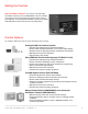
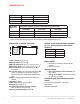
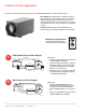


Terminal Description
* NOTE: The outer screws on each
terminal block secure the block to the
chassis. They are not used for wiring.
The six terminals for the left hand terminal block are:
FLOAT (2): External low-voltage water sensor or float
switch
DHUM: Compressor and fan operation for
dehumidification
R: DR65 24V output
FAN: Fan activation only for ventilation
C: DR65 24V output
External 24V devices can be powered from R and C
terminals (20VA max.)
The right hand terminal block in the above
figure is used only for interlocking a TrueDry
DR65 with an equipment fan. The three
terminals are:
Gt: Fan operation from thermostat
Rf: 24V from equipment fan
Gf: Fan operation from equipment fan
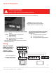
Wiring
Wire the TrueDRY
DR65 according to
the diagram that
applies to your
desired operation.
Follow this diagram for
ducted operation with the
onboard dehumidistat.
Two wiring terminal blocks are located on the exhaust end of the TrueDRY unit.
TrueDRY
HVAC
THERMOSTAT
GYWRRc
GYWR C
M33153
Gt
+
+
Rf
Gf
DHUM
+
+
R
FAN
C
FLOAT FLOAT
TrueDry DR65 Dehumidication System 69-2089EFS—12 7
CAUTION: Low voltage hazard.
Can cause equipment damage.
Disconnect HVAC equipment before beginning installation.