
DS06 Installation Instructions

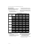
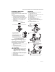
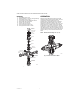
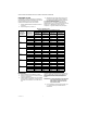
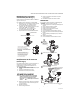
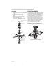
Table Of Contents

DS06 LOW LEAD CONTENT DIAL SET PRESSURE REGULATING VALVES
3 33-00014EF—03
Changing the Downstream
Pressure (See Fig. 1)
Remove the dust cap from the DS06. The DS06 is factory
set to 60 psi.
To adjust the outlet pressure to a desired setting:
1. Loosen the locking screw by turning counter-
clockwise (Do not remove this screw.)
2. Turn the adjusting knob counter-clockwise to
reduce pressure or clockwise to increase
pressure.
3. Lock the setting by turning the locking screw
clockwise .
4. Replace the dust cap over the dial.
Fig. 1. Changing outlet pressure.
Replacing the Cartridge (Fig. 2)
The working parts of the DS06, including diaphragm,
valve seat, strainer, and disk are all contained in a
replaceable cartridge. To replace the cartridge:
1. Close shutoff valve on inlet.
2. Release pressure on outlet side (e.g. through water
tap).
3. Close shutoff valve on outlet.
4. Loosen slotted screw (do not remove the screw).
CAUTION
To prevent injury and/or equipment damage,
loosen locknut and turn adjusting screw
counter-clockwise to remove spring
tension.
5. Slacken tension in compression spring by turning
counter clockwise until it does not move anymore.
6. Unscrew Bonnet.
7. Remove slip ring.
8. Remove cartridge using a pliers as a lever.
9. Reassemble bonnet in reverse order.
Recalibrate
If the dial knob assembly has been disassembled
recalibration is necessary.
1. Close shutoff valve on inlet.
2. Release pressure on outlet side (e.g. through water
tap).
3. Close shutoff valve on outlet.
4. Remove dust cap.
5. Loosen slotted screw (do not remove screw).
6. Fit pressure gauge.
7. Slowly open shutoff valve on inlet.
8. Set desired outlet pressure (e.g. 60 psi).
9. Align scale (e.g. 60 psi) in middle of viewing win-
dow.
10. Retighten slotted screw.
11. Slowly open shutoff valve on outlet.
Fig. 2. Replacing the DS06 cartridge.
LOOSEN LOCKING
SCREW ONE TURN
ADJUST SETPOINT AT THE DESIRED VALUE BY ACTUATING SELECTOR.
INLET PRESSURE (MAXIMUM): 250 PSI
REDUCED PRESSURE RANGE:
25 TO 90PSI 1/2 IN. TO 2 IN. SIZE
NOTE: DO NOT DISMANTLE KNOB
SET-POINT READOUT HAS BEEN CALIBRATED
IN THE FACTORY AND SET AT 60 PSI.
DISMANTLING THE SELECTOR KNOB WILL
CANCEL THIS CALIBRATION. RECALIBRATE
USING A PRESSURE GAUGE. SEE RECALIBRATION.
M35046
3
M35047
1
4
6
2
LOOSEN THE SETPOINT DIAL LOCKING SCREW.
UNSTRESS THE
PRESSURE SPRING
BY TURNING COUNTER-
CLOCKWISE .
UNSCREW THE BONNET WITH MT06A SERVICE TOOL.
REMOVE CARTRIDGE USING A PLIERS AS A LEVER.
REASSEMBLE BONNET IN REVERSE ORDER.
MT06A SERVICE TOOL
(ORDER SEPARATELY)
O-RINGS
WASHER
(LIP UP)
5
WHEN REASSEMBLING,
ENSURE O-RINGS AND
WASHER ARE PROPERLY
INSTALLED