ARENA / RANGER Copyright © 2008 Honeywell GmbH ● All Rights Reserved User Guide EN2Z-0906GE51 R0708
ARENA / RANGER USER GUIDE .
USER GUIDE ARENA / RANGER ARENA / RANGER 2.0 USER GUIDE Software License Advisory This document supports software that is proprietary to Honeywell GmbH, Honeywell Control Systems Ltd, and/or to third party software vendors. Before software delivery, the end user must execute a software license agreement that governs software use.
ARENA / RANGER EN2Z-0906GE51 R0708 USER GUIDE
USER GUIDE ARENA/ RANGER CONTENTS OVERVIEW ........................................................................................................................... ARENA / RANGER Versions.............................................................................. System Architecture ........................................................................................... START ARENA ..................................................................................................................
ARENA / RANGER USER GUIDE ALARM FORWARDING ........................................................................................................................... Create Alarm Forwarding ................................................................................... Create Destination......................................................................................... Create Trigger ...............................................................................................
USER GUIDE ARENA/ RANGER OVERVIEW ARENA is a Windows® based software package that provides an easy-to-use graphical interface to monitor and operate HVAC applications applying LonWorks technology. A typical application is, for example: • A Commercial building using plant controllers for primary plant control such as air handling units, heating circuits or boilers In ARENA, such a running application is also called “Site”.
ARENA / RANGER USER GUIDE ARENA also offers multi-level password protection to restrict access of unauthorized users. All adjustments to system operating parameters are logged by ARENA, together with users identification. This access restriction provides a very high degree of system protection against accidental or malicious damage. ARENA can be equipped with individual graphic data and will be able to display selected information in a graphical environment.
USER GUIDE ARENA/ RANGER TIGER / PANTHER TIGER / PANTHER LAN iLON 10 Dial-Out (Alarms) Dial-In (e.g. upon user request) Modem SERVAL SERVAL TIGER / PANTHER Supervisor ARENA COACH LAN TIGER / PANTHER TIGER / PANTHER or Modem* Dial-Out (Alarms) Dial-In (e.g.
ARENA / RANGER USER GUIDE All systems can operate individually and independently or together in a complete system. Definitions Site A customer installation of communicating controllers. Equals one COACH project.
USER GUIDE ARENA/ RANGER START ARENA 1. In Windows Start menu, click Programs, then click Centraline and ARENA2 or, click the CL Arena 2.0 icon on the desktop. ARENA is started and the ARENA Login screen is displayed. 2. Enter your User Name and your Password. 3. In Operation Mode, select: Text, if you want to operate ARENA in the common text-based way (Site tree visible).
ARENA / RANGER USER GUIDE For detailed description of the main window and its functions, please refer to “ARENA Environment “section.
USER GUIDE ARENA/ RANGER ARENA ENVIRONMENT Main Screen Description and Basic Functions Main Screen Description The Main screen provides two basic panes, the site selection pane, in the following simply named site tree, and the Information and Editing pane. Site Tree The site tree on the left displays all sites (local or remote) of ARENA in a hierarchical tree structure.
ARENA / RANGER USER GUIDE Fig. 2. Site Display Modes in Tree Depending on the current operating status (online= connected) or (offline= disconnected), the sites are indicated differently. A connected site is displayed in full color; a disconnected site is displayed in transparent color. A red triangle with exclamation mark may appear which indicates an unacknowledged alarm.
USER GUIDE ARENA/ RANGER Fig. 3. Example: Tree Item display in the Information and Editing pane Fig. 4. Example: Menu display in the Information and Editing pane Sizing the Pane Displays The size of the pane display can be varied by moving the separator horizontally to the left or right. ARENA will remember the corrected width when coming back or restarting the software.
ARENA / RANGER USER GUIDE Collapsing/Expanding the Site Pane The site pane can be collapsed (hidden) by clicking the arrow bar in the middle of the separator. The hidden site pane can be expanded (made visible) by clicking on the arrow bar on the left-handed separator in the main window. Tree Navigation You can navigate through the tree by clicking on tree items, or by clicking the plus/minus icons at the tree items.
USER GUIDE ARENA/ RANGER To edit item properties, select tree item, e.g. HEATING PLANT, and then select tab, e.g., Datapoints, and click item you want to edit. Example: Datapoint editing in the Information and Editing pane for a selected datapoint of a PANTHER controller.
ARENA / RANGER USER GUIDE Values can be edited by clicking on the corresponding value which opens a dialog for editing the value. Logout By clicking the Logout icon , you can logout. Context Sensitive Online Help Clicking on the Help icon displays the ARENA online help in PDF format. Basic Functions The properties of a selected item in the tree, for example, a PANTHER controller, are displayed on tabs on the right pane.
USER GUIDE ARENA/ RANGER Depending on the user privileges, data can be modified by clicking the appropriate buttons, such as Print, Save, Delete, etc, or by using allocated icons, for example the Configure icon of a datapoint. An underlined item in a list indicates that this entry links to a further dialog showing more details of the item. By clicking on the entry, you can edit details of the selected item.
ARENA / RANGER USER GUIDE Further Button Functions NEW / GO / SCAN / DELETE / others Those kind of specific buttons perform functions as the button name indicates in its functional context. Multiselection of Items Clicking the checkbox in the title line of a list, Simultaneously selects all entries in the list. In particular dialogs, multiple items can be selected by using the SHIFT or the CTRL key simultaneously with the mouse clicking.
USER GUIDE ARENA/ RANGER List Display Configuration A list configuration, for example of a datapoints list, always applies to all lists of the same kind (in this case all datapoints list) on the same level (site, device, plant, segment).
ARENA / RANGER USER GUIDE e. Click the upward or downward buttons. 4. Click the OK button so save settings or continue with: a. Setting the sort order within a column and/or (step 5) b. Setting the default filter display (step 7). 5. To set the sort order within a column, click the Sort Order tab. 1 1 Under Available columns, all columns of which sort order can be set, are listed. Under Sorting, all columns and their current sort sequence are listed. NOTE: By default, all columns are sorted ascending.
USER GUIDE ARENA/ RANGER Under Filtering, all displayed columns of the list and their current filter setting is shown. By default, no particular filter is used (All), that is, all items are displayed. Depending on the column property, e.g. Name or Value/Unit, you can select different particular items which you want to filter for display. You can create a new filter which can be selected here after it has been created elsewhere (see “Create New Filter” section). a.
ARENA / RANGER USER GUIDE 1. To apply a filter, click in the field and do one of the following: a. select the filter criterion, for example, ´Digital` in the Type column if you want to display digital datapoints only. Or, b. if no filter criteria are available, click New Filter c. In the Select Wildcard dialog box, enter the Filter string by using the asterisk and click OK button. For example, the filter string ´DHW*` displays only datapoints of which name starts with ´DHW`.
USER GUIDE ARENA/ RANGER Usage of Illegal Characters It is forbidden to use the following characters when working with ARENA: • Slash character ”/” in alias names • Special characters and Umlauts Ä, Ö, Ü, ä, ö, ü in site names when creating sites. After creation of the site, you can change a site name in the tree using these characters. Using any of these characters may result in an unexpected behavior of ARENA.
ARENA / RANGER USER GUIDE ARENA Service The underlying software of ARENA is the service, named ARENA service or simply service. This service is accessible in the system tray and is indicated there as square service icon .
USER GUIDE ARENA/ RANGER Service Starts / stops ARENA and shows its status information (Running, Stopped). In addition, an optimize disc space command is available. Exit Stops the service and shuts down ARENA. Show ARENA Version Information 1. In the system tray, right-click on the Service icon. 2. In the context menu, click About. RESULT: The About CentraLine ARENA information box displays showing the actual used version of ARENA. 3. After you have read the version information, click OK.
ARENA / RANGER USER GUIDE 3. Right to the File field, browse to the folder where you want to save the export file. 4. Click Export button. 5. Click Close button. Manage Library With this function, you can manage the library content and the view of the library components (configurable standard applications, room controls, segments). To start and work with the library manager, do the following: 1. In the system tray, right-click on the Service icon. 2. In the context menu, click Manage Library.
USER GUIDE ARENA/ RANGER can include new library components or segment updates of existing library components. NOTE: You cannot create CSL files by your own. After the import is finished all library components, included in the CSL file, are added to the list. 5. Apply step 3. for the imported library components. 6. Click Save, and then click Close. Licensing 1. In the system tray, right-click on the Service icon. 2. In the context menu, click Licensing.
ARENA / RANGER USER GUIDE Password Allows the user to change its own password. Trending Provides basic pre-setting functions for executing trends. NOTE: To exit the configuration menu, click the Home button . USER ADMINISTRATION The user administration is used for creating users and assigning particular user privileges (roles) to the users. Administration also includes editing and deleting of users. Roles and Privileges A role determines the privileges that the user will have when working with ARENA.
USER GUIDE ARENA/ RANGER In addition, a password for each user must be issued for secure operation of ARENA. Finally, for comfortable remote operation, a user can have an Auto-Logon property assigned that allows logging into the remote site without entering Login name and password again. Login, Information Access and Password Handling When entering a site, you must login with user name and password. After logged in, you will see all information that you have access to, based on your role.
ARENA / RANGER USER GUIDE Create New User 1. Click Create new user button. RESULT: EN2Z-0906GE51 R0708 The Edit/Create new user dialog is displayed.
USER GUIDE ARENA/ RANGER 2. In User Name, enter the user name. 3. In Password, enter the password. 4. In Password, confirm the password by entering the same password. NOTE: When creating sites that use incoming connections, It is strongly recommended to change the password of default user names such as manager, keeper, etc. which by default reads the same as the user name. 5. In Role, select the role for the user. 6. In Comment, enter a comment if desired. 7.
ARENA / RANGER USER GUIDE 12. Click Save button. RESULT: The created user is displayed in the Users list. Edit User 1. In the Users list, click on the user name you want to edit, then click the Edit button in the corresponding line. RESULT: EN2Z-0906GE51 R0708 The Edit/Create new user dialog is displayed.
USER GUIDE ARENA/ RANGER 2. Edit desired properties. For description of the properties, please refer to the “Create New User” section. 3. Click Save button. Delete User 1. In the Users list, click on the user name you want to delete, then click the Delete button in the corresponding line. RESULT: The user is deleted and removed from the list.
ARENA / RANGER USER GUIDE 1. Hover the cursor over the Configuration icon menu. 2. 3. 4. 5. EN2Z-0906GE51 R0708 and click Password in the In Old password, enter the current password. In New Password, enter the new password. In Repeat new password, enter the new password. Click OK button. The password is changed. NOTE: You can only change your own password.
USER GUIDE ARENA/ RANGER SITE MANAGEMENT ARENA supports the connection to up to 4 local sites. Local Site Support ARENA supports remote sites, which are connected through iLON 10 or through another remote ARENA. That ARENA is called Supervisor ARENA. Remote Site Support Ranger supports remote sites, which are connected through iLON 10 only. ARENA supports remote sites, which are connected through iLON 10. Only one ARENA can be connected at the same time to one iLON 10.
ARENA / RANGER USER GUIDE connection is automatically terminated. Automatic disconnection prevents “forgetting to close a connection”. It is used for modem connections only. NOTE: If a remote site is disconnected, the supervisor ARENA has a time out of up to 2 minutes before the tree gets refreshed to indicate offline state. Site Combinations The max. of 100 sites can be arranged in one supervisor ARENA system.
USER GUIDE ARENA/ RANGER – Settings such as graphic, alias, etc. done in the supervisor ARENA apply only to the supervisor ARENA itself and are independent of settings done in a local ARENA – Online value changes through Remote control: last wins – Trending • Supervisor ARENA Supervisor ARENA Æ ARENA (remote iLON 10 via Modem) * 2 PANTHER / TIGER Remote ARENA Modem LON Bus iLON 10 SERVAL SERVAL SERVAL Fig. 8.
ARENA / RANGER USER GUIDE by Windows. Setting up a remote access connection is done via the Windows Creating New Network Connection procedure. Remote ARENA via serial modem* For modem dial-up the Westermo TD33 is supported. The modem connection is only supported for dial into a remote iLON 10. CAUTION Do not switch off or disconnect a modem when operating a modem-connected site. This causes a malfunction and as a result the need to reboot the PC. TIP: Connect PC and modem to the same power supply.
USER GUIDE ARENA/ RANGER User Authentication and Access on Remote Site Initial Setup of the Remote Site’s Communication Settings The user is identified by its user name and password for the modem or LAN connection. The configuration of the ILON 10 needs to be done via the Supervisor ARENA. In order to save the iLON 10 configuration in ARENA it is necessary to be connected to it.
ARENA / RANGER USER GUIDE when trend data are requested for display from the remote site and this data is not already available in the Supervisor ARENA’s trend database. Alarm data upload from sites of a remote ARENA Alarm data stored on the remote site is unloadable and can be merged into the Supervisor ARENA’s alarm database upon any user request (manual upload).
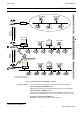
USER GUIDE ARENA/ RANGER • Remote through iLON 10 Creates a remote site without ARENA. Site connection is established via modem or TCP/IP. This site type must be selected if you want to connect to a site without ARENA. NOTE: iLON 10 must be accessible for configuration in order to save the created site. TIGER / PANTHER Supervisor ARENA Monitoring (Home) Site LON Bus SERVAL LAN / Modem TIGER / PANTHER Remote Site LON Bus iLON 10 SERVAL SERVAL SERVAL Fig. 11.
ARENA / RANGER USER GUIDE TIGER / PANTHER Supervisor ARENA Monitoring (Home) Site LON Bus SERVAL LAN / Modem / VPN TIGER / PANTHER Remote ARENA Remote Site LON Bus SERVAL SERVAL SERVAL Fig. 12. “Remote Through ARENA” Site Type 3. Click the Add button. Depending on the selected site type, individual dialog pages display for setting up the site. When creating a local site, continue with “Create Local Site” section.
USER GUIDE ARENA/ RANGER NOTE: It is forbidden to use any of the Umlauts Ä, Ö, Ü, ä, ö, ü in site names because this may result in an unexpected behavior of ARENA. b. In Site Details, enter optional additional description, e.g. customer name, address, etc. 3. Under Local Connection, do the following: a. In Connect through, select the LON interface to be used to establish the connection. One LON interface card is required per local site and ARENA supports max. 4 LON interface cards at maximum.
ARENA / RANGER USER GUIDE 2. Under General, do the following: a. In Site Name, enter a name for the site. NOTE: It is forbidden to use any of the Umlauts Ä, Ö, Ü, ä, ö, ü in site names because this may result in an unexpected behavior of ARENA. b. In Site Details, enter optional additional description, e.g. customer name, address, etc. c. In Connect Through, select connection type from: – TCP/IP ARENA connects to the iLON 10 via TCP/IP (LAN) – Modem ARENA connects to the iLON 10 via modem d.
USER GUIDE ARENA/ RANGER Monitoring (Home) Site (A) Supervisor ARENA Site A SITE Configuration and iLON Access Enabled: must be checked iLON 10 address settings: IP address, subnet mask, gateway address Outgoing Connection Incoming Connection SITE Configuration Enabled: checked for receiving alarms and iLON configuration changes unchecked: for maintenance by ARENA only iLON Settings MAINTENANCE CALLS LAN iLON Configuration User name: default = ilon Password: default = ilon ALARMS PANTHER / TIGE
ARENA / RANGER USER GUIDE 5. Under Outgoing Connection to Remote Site do the following: a. Check Enable if you want to use ARENA for dialing-in to a remote site. b. Uncheck Enable if ARENA is only used for receiving alarms.
USER GUIDE ARENA/ RANGER a. Check Enable if you want the supervisor ARENA enable to receive alarms via the iLON 10 on the remote site. b. Uncheck Enable if you not want the supervisor ARENA to receive alarms. Checking Enable is necessary if you want to customize the iLON 10 by overwriting the default configuration with the settings entered in Outgoing connection to Remote Site. Unchecking Enable is recommended if you want to view the site without the necessity of changing the iLON 10 configuration. 7.
ARENA / RANGER USER GUIDE iLON 10 has been reached and configured successfully, ARENA saves the site configuration. 9. Create Remote Site through iLON 10 via Modem The following descriptions refer to an Example of a typical scenario of a Supervisor ARENA – iLON 10 configuration via modem as shown in the graphic below.
USER GUIDE ARENA/ RANGER 11. Under Outgoing Connection to Remote Site do the following: a. Check Enable in order to access the remote iLON 10 site. When unchecking this option you cannot access the site. NOTE: When restarting the ARENA Service (see “ARENA Application” section), all iLON 10 will be automatically connected, independent of the Enable setting. Automatic connection also occurs if a graphic contains a datapoint of the remote site. b.
ARENA / RANGER USER GUIDE a. Check Enable if you want the supervisor ARENA enable to receive alarms via the iLON 10 on the remote site. b. Uncheck Enable if you want the supervisor ARENA not to receive alarms. c. Checking Enable is necessary if you want to customize the iLON 10 by overwriting the default configuration with the settings entered in Outgoing connection to Remote Site. Unchecking Enable is recommended if you want to view the site without the necessity of changing the iLON 10 configuration. d.
USER GUIDE ARENA/ RANGER In the iLON 10 configuration (section "PPP"), this setting will be stored as "Modem Init String". The default is E0Q0V1S0=0&C1M1&W.This setting works for the supported modems. Wait for dial tone before calling If enabled, the modem connected to the iLON 10 will wait for the dial tone. Default = yes. If no connection can be established, the telephone installation might not provide a correct dial tone. In this case, disable the option.
ARENA / RANGER USER GUIDE Create Remote Site through ARENA 1. If not already done, select “Remote Site through ARENA” in New site of type on the Sites Overview pane, and then click the Add button. 2. Under General, do the following: a. In Site Name, enter a name for the site. NOTE: It is forbidden to use any of the Umlauts Ä, Ö, Ü, ä, ö, ü in site names because this may result in an unexpected behavior of ARENA. b. In Site Details, enter optional additional description, e.g. customer name, address, etc.
USER GUIDE ARENA/ RANGER If TCP/IP has been selected, continue with step 4. 1 If Modem has been selected, continue with step 6. 1 If VPN has been selected, continue with step 8. 1 NOTE: Only Microsoft VPN connections are supported. 4. Create Remote Site through ARENA via TCP/IP The following descriptions refer to an Example of a typical scenario of a Supervisor ARENA – Remote ARENA configuration via LAN as shown in the graphic below.
ARENA / RANGER USER GUIDE Dial-up connections are typically used to connect to an ISP (internet service provider) when the mail server is not reachable via LAN. NOTES: – Yahoo cannot be used as ISP because there are issues on the provider side concerning external email access. Use an alternative ISP. – ARENA shows all dial-up connections on your PC here, except the ones used to connect to remote sites.
USER GUIDE ARENA/ RANGER a. In User Name, enter the user name. b. In Password, enter the password for the user. NOTES: – User name and password of the supervisor ARENA must match the user name and password under Incoming connection from remote site on the remote ARENA. – On both ARENAs, user name and password must comply with the Windows network requirements. If necessary, please contact the I.T. administrator for detailed information.
ARENA / RANGER USER GUIDE c. In Remote Site Address or IP Address, enter the URL or the IP Address of the remote ARENA PC. Under Connect, select Directly if you want to connect to the remote ARENA without an ISP (Internet Service Provider, see NOTES below). Select Dial to ISP first using if you want to connect via ISP (dial-up). From the list, select the ISP. If desired add or remove ISP connections using the buttons. To edit ISP properties, click Connection Settings dialog box.
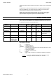
USER GUIDE ARENA/ RANGER Cross Reference of iLON 10 Settings and ARENA Settings ARENA configures the iLON 10 when creating the site (see in “Create Site” section). If the iLON 10 configuration, e.g. user name or password, was changed manually afterwards, the ARENA settings must be changed accordingly. If ARENA settings and the iLON 10 settings are out of sync it may happen that the iLON 10 cannot be contacted anymore. For the accommodation of settings, use the following table.
ARENA / RANGER USER GUIDE Hayes AT command set. Security Settings page of iLON 10 iLON 10 Setting ARENA Setting Comment Allow HTTP Access - Has to be enabled to allow configuration changes. HTTP Access -> User Name iLON 10 Settings -> User Name Used to authenticate ARENA when it tries to do configuration changes on the iLON 10. HTTP Access -> Password iLON 10 Settings -> Password Used to authenticate ARENA when it tries to do configuration changes on the iLON 10.
USER GUIDE ARENA/ RANGER 3. Edit desired site details. For detailed description of the site properties, click relevant subsection in the “Create New Site” section. NOTE: It is forbidden to use any of the Umlauts Ä, Ö, Ü, ä, ö, ü in site names because this may result in an unexpected behavior of ARENA. Delete Site 1. Show Sites Overview as described in the “Show Sites Overview” section. 2. Click on site you want to delete. 3. Click Delete Site button.
ARENA / RANGER USER GUIDE Connect / Disconnect Site In the tree, connected sites (subsystem, controller, etc.) are displayed in light green color. Disconnected sites with its items (subsystem, controller, etc.) are displayed in light gray color. 1. In the tree, right-click the site, you want to connect to /disconnect from. Fig. 18. Example: Connecting to Site Fig. 19. Example: Disconnecting from Site 2. If you want to connect to a site, click Connect Site icon.
USER GUIDE ARENA/ RANGER 5. If you want to disconnect from a site, click Disconnect Site icon. 6. If you want to disconnect all local or remote connections, click Physically Disconnect Sites icon. Timeout after Disconnection If the remote site of an ARENA-ARENA via LAN site combination is disconnected, the supervisor ARENA has a time out of up to 2 minutes before the tree gets refreshed to indicate offline state. Create Subsystem 1.
ARENA / RANGER USER GUIDE GRAPHICS View/Edit SERVAL Graphics By default, ARENA displays a SERVAL graphic when clicking on the corresponding SERVAL controller in the tree. The graphic is shown on the Graphics tab. Modifications can be done for the fan switch by selecting the value from the dropdown listbox. View/Edit Standard Segments To view/edit a standard segment, do the following: 1. Expand the tree, and then double-click the controller´s plant that contains the segments.
USER GUIDE ARENA/ RANGER Example 2: Boiler 1 This function allows configuring the boiler segment by entering/changing values according to your needs on the Functions and Equipment tabs.
ARENA / RANGER USER GUIDE DATAPOINTS Overview Datapoints are available on Site, System, Controller, Plant, and Segment level. Depending on the level, the datapoint list display differs in the number and kind of columns (datapoint properties).
USER GUIDE ARENA/ RANGER In the datapoints list, you can do the following: • Display certain datapoints by applying a filter as described under “Apply Filter for Display” in the “Basic Functions” section. • Enter an alias name for a datapoint. Please refer to the “Enter Alias Name for Datapoint” section. • Override the current datapoint value. Please refer to the “Override Datapoint Value” section. • View and change datapoints properties. Please refer to the “View/Change Datapoint Properties” section.
ARENA / RANGER USER GUIDE 3. To display certain datapoints, apply a filter as described under “Apply Filter for Display” in the “Basic Functions” section. 4. To enter an alias name for a datapoint, please refer to the “Enter Alias Name for Datapoint” section. 5. To override the current datapoint value, please refer to the “Override Datapoint Value” section. 6. To view and change datapoints properties, please refer to the “View/Change Datapoint Properties” section. 7.
USER GUIDE ARENA/ RANGER 3. Click OK. The new name is reflected in the Name column. View/Change Datapoint Properties 1. In the Name column, click the datapoint´s name. The Datapoint Properties page displays. Under Name, the properties and under Value/Unit the corresponding values are shown. Values out of range are grayed. In this dialog, you can do the following: • Change a value of a property • Enter an alias name for a property name • Print properties with their values.
ARENA / RANGER USER GUIDE 2. To change a value, click on the value in the Value/Unit column. In the Value dialog box, enter new value in the New Value field. Click Apply button, then click OK button. at the 3. To enter an alias name for a property name, click the Configure icon end of the row. In the Configure dialog box, enter the alias name in the Alias field. Click OK. NOTE: It is forbidden to use the slash character ”/” in alias names because this may result in an unexpected behavior of ARENA. 4.
USER GUIDE ARENA/ RANGER 2. In the filter field, select (all) or Yes. All datapoints in Manual override are indicated by a checkmark. All others (if all are displayed) are not checked. Print Datapoints List 1. Select all datapoints in the datapoints list (Multi-selection using CTRL key is possible), you want to add to the printed list. 2. Click Print. The list is built up in a new dialog. 3. Click Print.
ARENA / RANGER USER GUIDE 4. In the Print dialog box, select the printer and desired options and click Print. ALARMS Overview Multi Site Alarming Support Manual Alarm Clearing Determine Alarm Reason Link to the Alarm Destination On a supervisor ARENA, alarms can be collected centrally from all sites. The user can “artificially” create a going alarm for a selected coming alarm. If the user knows for sure that an alarm is gone, he can clear it. You can navigate directly to the alarm source.
USER GUIDE ARENA/ RANGER • Site Site name where the controller is located that has raised the alarm. Comes from the controller file (Panther / Tiger Controller) • Device Controller name • Alarm Reason Shows the alarm reason, for example, ´min alarm` • Time stamp Time when the alarm was raised • Cleared at Timestamp when the alarm reason went away, for example, last 24 hours. In the global alarm list, this is shown as grayed checkbox. If the alarm is cleared, the checkbox is checked, otherwise unchecked.
ARENA / RANGER USER GUIDE Email address. • Acknowledged by station ARENA that acknowledged the alarm • Item Name Alarm source (datapoint) that has caused the alarm. – Shows ´System` when the alarm is a system alarm – Shows the datapoint name for point alarms • Item Value: value/status of the datapoint when the alarm has occurred. – Shows N/A when the alarm is a system alarm that does not provide an item value.
USER GUIDE ARENA/ RANGER NOTE: Both views can be configured separately. Alarm Handling When the controller is connected to ARENA, alarms are received automatically as soon as ARENA is installed or the remote site has been configured correctly using ARENA's site configuration. NOTES: Dial-up sites will automatically connect to the supervisor PC in case of a critical alarm. Alarms from LAN sites can only be received if the LAN site is connected explicitly.
ARENA / RANGER USER GUIDE • View alarm details of a single alarm Please refer to the “View Alarm Details of Single Alarm” section.
USER GUIDE ARENA/ RANGER 7. To delete the alarm, click the Delete button. This flags the alarm in the database as ´deleted`. Print Alarm List 1. Select all alarms in the global datapoints list (Multi-selection using CTRL key is possible), you want to add to the printed list. 2. Click Print. The list is built up in a new dialog. 3. Click Print. 4. In the Print dialog box, select the printer and desired options and click Print. Acknowledge Alarms 1.
ARENA / RANGER USER GUIDE Delete Alarms 1. Show Global Alarm List as described in the “Show Global Alarm List” section. 2. Click on alarm you want to delete (Multiselection using CTRL key is possible). 3. Click Delete button. This flags the selected alarms in the database as ´deleted`. Upload Alarms Alarms can be uploaded from different source sites and for a definable time range. 1. Show Global Alarm List as described in the “Show Global Alarm List” section. 2. Click Upload Alarms button.
USER GUIDE ARENA/ RANGER ALARM FORWARDING Alarm forwarding is possible to printers, eMail or mobile phone (via eMail), or service ARENAs. Alarm segregation allows forwarding alarms to different destinations based on definable criteria such as: • Trigger (information of the alarm itself), such as: Critical / Non-Critical, site on which the alarm occurred, datapoint names, e.g. all points that start with “Heat”, and many more.
ARENA / RANGER USER GUIDE Create Alarm Forwarding An alarm forwarding will be created with the following major steps: 1. Create Destination (see “Create Destination” section) a. Define destination for sending and receiving alarms b. Define alarm message c. Define acknowledgement message d. Define ´Advanced` options 2. Create Trigger (see “Create Trigger” section) a. Define Condition that initiates the alarm forwarding 3. Create Forwarding (see “Create Forwarding” section) a.
USER GUIDE ARENA/ RANGER 3. On the General tab, select the destination In Destination Type under: • Email • Printer • Arena Depending on the selected destination type, individual dialog pages display for setting up the destination. When creating an email destination, continue with step step 4 under “Email Destination Type”. 1 When creating a printer destination, continue with step 11 under “Printer Destination Type”.
ARENA / RANGER USER GUIDE a. In Destination Name, enter descriptive text for your email destination. b. In From, enter the E-mail address for ARENA. This is the sender’s mailbox address. Note that each ARENA installation must have its own mailbox. c. In To, enter the E-mail address(es) for the recipients of the alarm. Multiple addresses can be separated by semicolon. d. In Cc, specify the E-mail address(es) for the recipients to which the alarm information should be copied.
USER GUIDE ARENA/ RANGER check this by selecting Connect to / Show all connections from the Windows Start menu. Then open the properties of the connection. Sending Alarms (SMTP) NOTES: – The SMTP (Simple Mail Transfer Protocol) is preferentially used for sending/forwarding emails. – To get information about the SMTP settings, go to the web site of the local ISP, invoke the Help function and search for the required information.
ARENA / RANGER USER GUIDE a. In Server Name or IP, enter the address of the POP3 server (name or IP address) you want to use to receive emails, e.g. pop3.web.de”. b. In Port, you must change the port used to receive emails via POP3 if your ISP uses another port than the default port 110. Change it accordingly, if necessary. NOTE: It may happen, that an anti-virus software may block the port 110 which is necessary for receiving emails.
USER GUIDE ARENA/ RANGER a. Click in the Message list and change, edit or delete text at the desired position. b. In the Message list, click at the position where you want to insert a predefined text component (placeholder) c. Select the corresponding field in the Fields drop-down listbox and then click the Insert button. The placeholder, indicated by two pound characters #, is inserted at the cursor position. 6. Select the Acknowledgement Message tab.
ARENA / RANGER USER GUIDE 7. Select the Advanced tab. Advanced Tab Behavior on Connection Failure a. In Check for new mails every … (minutes), enter minutes after which the server should check for new email acknowledgements. This function requires a POP3 server to be setup. b. In Retry count, enter the number of attempts ARENA should make to reach the Email server. When ARENA still cannot reach the Email server after retrying, it stops any further attempt until a new alarm comes in. c.
USER GUIDE ARENA/ RANGER NOTE: In order to avoid spamming, some Email providers restrict sending emails in short intervals. This time interval can be, for example, up to 15 minutes. This restricting interval may result in the loss of sent alarm emails. Please check if your Email provider demands on such restrictions. It is recommended to choose an Email provider that has such restrictions. Otherwise alarm emails may not reach the recipient. These restrictions also pertain to alarm showers. 10.
ARENA / RANGER USER GUIDE Layout a. Default, if you want the alarm columns to be distributed across the available space on the paper. b. Select Userdefined, if you want the columns to be distributed across the available space on the paper according to a default layout grid which is displayed below. Clicking the Load from Alarm Detail View Columns button loads the current detailed view column configuration of the top level entry in the site tree and replaces the default grid below.
USER GUIDE ARENA/ RANGER a. In Arena, select the remote ARENA you want to forward the alarms. b. In Destination name, enter a descriptive text for the ARENA. 16. Click Advanced tab. Advanced Tab Behavior on Connection Failure a. In Retry count, enter the number of attempts ARENA should make to reach the remote ARENA. When ARENA still cannot reach the remote ARENA after retrying, it stops any further attempt until a new alarm comes in. b.
ARENA / RANGER USER GUIDE Create condition a. In Property, select the property, for example ´alarm class` b. In Comparator, select the comparator, for example ´=` c. In Condition, select the condition for example ´System Alarms`. This condition results in the following: All system alarms will be forwarded. By default, the triggers ´All critical alarms` and ´All uncritical alarms` are already available in the triggers list. d. Click the Insert Condition button.
USER GUIDE ARENA/ RANGER e. In Trigger Name, enter a name for the trigger, for example, ´System Alarms`. f. Click OK button. The trigger is displayed in the Trigger List. g. Continue with finally creating the forwarding as described in the “Create Forwarding” section. Create Forwarding 1. Hover the cursor over the Configuration menu icon and click Alarming in the configuration menu. 2. To create a forwarding, click the Forwarding tab, and then click the Create new Forwarding button.
ARENA / RANGER USER GUIDE b. In Destination, select the destination to which the alarms should be forwarded. c. Check Enabled if the forwarding should be active and check the days on which the triggered alarms should be forwarded to the selected destination. d. Enter the time range for each day. 4. Click the Advanced tab. Advanced Tab Settings a. Check Delay notification if the alarms should be forwarded when the alarm buffer has reached the number of alarms entered in Buffer. b.
USER GUIDE ARENA/ RANGER SETTINGS Overview Settings, also called parameters, are available on project, plant, and controller level. Settings can be uploaded from the PANTER / TIGER controller. From the SERVAL controller settings upload is not possible. Settings can be modified by value and name (alias) and a list for multiple settings can be printed. Depending on the level, the settings list display differs in the number and kind of columns (settings properties).
ARENA / RANGER USER GUIDE In the settings list, you can do the following: • Enter an alias name for a setting. Please refer to the “Enter Alias Name for Setting” section. • Modify the current setting value. Please refer to the “Modify Setting Value” section. • Upload Parameter Text List… Please refer to the “Upload Parameter Text List” section. • View and change Setting properties. Please refer to the “View/Change Settings Properties” section. • Print Settings list.
USER GUIDE ARENA/ RANGER 9. To configure the list display, please refer to “List Display Configuration” in the “Basic Functions” section. Enter Alias Name for Setting Group/ Single Setting NOTE: It is forbidden to use the slash character ”/” in alias names because this may result in an unexpected behavior of ARENA. You can manually change each number of a setting group or a single setting with a more descriptive name.
ARENA / RANGER USER GUIDE 7. At the end of setting row, click the Configure icon . 8. In the Configure dialog box, enter the alias name in the Alias field. 9. Click OK. The new name is reflected in the Name column. Modify Setting Value 1. In the tree, click the application, for example, HT02. 2. On the right pane, click the Settings tab. The setting groups are displayed. In this view you do not see the values of the settings.
USER GUIDE ARENA/ RANGER 3. Click the number of the group in the Name column. 4. In the Value/Unit column, click the value of the setting you want to change 5. In the Value dialog box, enter the new value in the New Value field. 6. Click Apply. 7. Click OK. The setting value is updated as displayed in the list.
ARENA / RANGER USER GUIDE Upload Parameter Text List When uploading a parameter text list, the setting groups and the single settings described by numbers are replaced with the more descriptive names. For example, the number 32 is replaced with Alarm 1 → Alarm. 1. In the tree, click on the controller. 2. On the right pane, click on the Settings tab. 3. Below the list, click on the Upload Parameter Text List button. 4.
USER GUIDE ARENA/ RANGER settings of a setting group, see “Modify Setting Value” section), you want to add to the printed list. 2. Click Print. The list is built up in a new dialog. 3. Click Print. 4. In the Print dialog box, select the printer and desired options and click Print.
ARENA / RANGER USER GUIDE Time Programs T Overview Time programs are for setting time sequences for controller operation. For example, setting HVAC start and stop times. Time programs implement these command schedules. A PANTHER / TIGER controller can have a maximum of 20 time programs. Each time program specifies a list of points to command and a weekly schedule.
USER GUIDE ARENA/ RANGER Date Overrides Time Program Names You can assign temporary schedules using the global schedule to replace daily schedules when holidays or other events occur that require different times and commands. Through application engineering, a PANTHER / TIGER controller can have at max. 13 time programs. By default, they are denoted as follows: • • • • • Heating Circ. 1 Heating Circ. 2 Dom.
ARENA / RANGER USER GUIDE Daily schedules Each daily schedule consists of several daily schedule types. For example, the RoomControl time programs include: – Weekday – Weekend – Global When selecting a daily schedule type, the settings are displayed on the right and can be edited.
USER GUIDE ARENA/ RANGER Weekly schedules A weekly schedule contains the daily programs for each day of the week: – Wordday – Weekend By default, Monday through Friday have the daily schedule ´Workday` assigned, Saturday and Sunday have the daily schedule ´Weekend` assigned. When selecting the Weekly schedules folder in the tree, the whole week is shown in table format (summary view). Each weekday´s settings can be edited by assigning the daily program to the weekday and setting the switchpoints per day.
ARENA / RANGER USER GUIDE When selecting the weekday in the tree, the daily program settings of the weekday are displayed on the right (detailed view).
USER GUIDE ARENA/ RANGER Yearly schedules Daily schedules are assigned to each day of the week in the weekly schedule. The weekly schedule is automatically repeated every week and creates the normal yearly schedule. The yearly schedules can be changed for a specific period by assigning different daily schedules to particular weekdays of the desired period. Example: The yearly schedule consists of the weekly schedules ´workday` and ´weekend`.
ARENA / RANGER USER GUIDE 2. Click Edit Datapoints. The Edit Datapoints dialog box displays. 3. In Default Occupied Value, enter the value in degrees Celsius for the occupied state. 4. In Default Unoccupied Value, enter the value in degrees Celsius for the unoccupied state. 5. Check Optimization checkbox, if you want to apply optimization. For detailed description of Optimization, please refer to step 3 in the “Create Daily Schedule” section. 6. Click OK button.
USER GUIDE ARENA/ RANGER 3. Add switchpoints to the blank daily schedule by doing one of the following (steps a and i) : a. On the right, click in the time table row (time), where you want to make the switchpoint start, then right-click and click Create. The Edit Value dialog box displays. Fig. 21. Edit Value dialog box example for Heating Circ.
ARENA / RANGER USER GUIDE Fig. 22. Edit Value dialog box example for Room Control time program b. In Value, do the following: c. For Heating Circuit time programs, keep the default value as defined in Edit Datapoints or modify the value. d. For RoomControl time programs, select the value under – Occupied The controller operates according to the “occupied” heating and cooling setpoints. This is the normal operating condition for a room or zone when it is occupied.
USER GUIDE ARENA/ RANGER Or, h. Copy switchpoints from another daily schedule to the new daily schedule as follows: i. Right-click on the new daily schedule. j. Select Copy switchpoints from, then click on daily schedule from which you want to copy the switchpoint settings, for example, Workday. The copied settings are reflected on the daily schedule time table on the right. 4. Click Save button on top of the Schedules tree.
ARENA / RANGER USER GUIDE 3. Change the settings as desired. 4. Click OK button. The time table indicates the updated settings according to your changes. Rename Daily Schedule 1. In the Schedules tree, expand the tree and right-click on the daily schedule you want to rename 2. Click Rename. 3. Change the flashing name in the tree and press ENTER key. 4. Click Save button on top of the Schedules tree. Delete Daily Schedule 1. In the Schedules tree, right-click on the daily schedule, you want to delete.
USER GUIDE ARENA/ RANGER Note that ´Weekend` switchpoints will be deleted and replaced by the Workday switchpoints. 3. Click Save button on top of the Schedules tree. Copy Switchpoints from another Daily Schedule See “Create Daily Schedule” section. Assign Daily Schedule to Weekday 1. In the Schedules tree, right-click on the daily schedule you want to assign to a particular weekday. 2. Select Assign to Weekday, and then click on the weekday you want to assign the daily schedule.
ARENA / RANGER USER GUIDE Weekly Schedules IMPORTANT Settings and changes made in daily schedules, weekly schedules and yearly schedules do only apply to the allocated time program, not any other time program(s). By default, the weekly schedule has the ´Workday` and ´Weekend` daily schedules assigned. These assignments can be changed by selecting the Global daily schedule or user-defined daily schedules to particular weekdays of a normal week.
USER GUIDE ARENA/ RANGER b. Or, right-click on the switchpoint area, then click Edit and change settings in the Edit Value dialog box. c. Or, enter settings in the enabled Value, Optimization, Start time and End time fields on the top. 5. To add new switchpoints, click in the table row (time), where you want to make the switchpoint start, then right-click and click Create. For details see “Create Daily Schedule” section, step 3. 6.
ARENA / RANGER USER GUIDE 9. Click Save button on top of the Schedules tree. Yearly Schedules IMPORTANT Settings and changes made in daily schedules, weekly schedules and yearly schedules do only apply to the allocated time program, not any other time program(s). The yearly schedules can be changed for a specific period by assigning different daily schedules to particular weekdays of the desired period. Example: The yearly schedule consists of the weekly schedules ´workday` and ´weekend`.
USER GUIDE ARENA/ RANGER The time range is displayed below. The weekdays show their assigned daily schedules and their source. Source shows the time schedules where the assigned daily schedule is originally created, that is, either the weekly schedule or when assigning another daily schedule to a weekday here (override), the yearly schedule. 3. To assign another daily schedule to a weekday, right-click on the weekday, select Assign, then click the daily program, for example, ´Weekend`.
ARENA / RANGER USER GUIDE The assigned daily schedule is shown in the Assigned schedule column. In the Source column, the overriding daily schedule is indicated by the entry ´Yearly schedules`. 4. Repeat step 3 for the desired weekdays of the displayed time range. 5. Click Save button on top of the Schedules tree.
USER GUIDE ARENA/ RANGER 3. In the device list, click controllers you want to override with the global time program. 4. In the calendar, set the time period in which you want to apply the global time programs by using the Previous, Previous fast, Next and Next fast buttons. 5. Click the Scan button.
ARENA / RANGER USER GUIDE After scanning is finished, existing override dates are shown in the calendar as follows: • Gray Date is overridden by another global schedule in at least one of the selected time programs • White Date is overridden by a yearly schedule other than global in at least one of the selected time programs • Blue Date is overridden by another global schedule of the yearly schedule in at least one of the selected time programs NOTE: When multiple time programs (controllers) are selected
USER GUIDE ARENA/ RANGER TRENDING AND TRENDS Definition Trending means to record value changes of selected datapoints and show the developing of the values for a definable time interval in a chart or table. Fig. 23. Trend Example Trend Types ARENA allows 2 ways of trending: Historical Trend The trended datapoint values are retrieved from the ARENA database which can contain values of all levels (station, site, and controller). In the first step, the datapoint values are recorded.
ARENA / RANGER USER GUIDE You can define a time window (“Last xx minutes”) and a time range (“Stop after yy hours”). ARENA will automatically displaying the controller values. After the elapse of the time window, the oldest values will begin disappearing and new values will be added on. This will be continued until the time range has elapsed. Thus, you are shown the actual values for the last xx minutes until yy hours have elapsed.
USER GUIDE ARENA/ RANGER NOTE: Add only those datapoints to trend which you really want to trend since trending increases bus traffic and has negative impact on the system performance. 1. Hover the cursor over the Configuration menu icon and click Trending in the configuration menu. The Data Collection pane displays. On the Data Collection pane, you can select the datapoints to be set in trend and you can remove datapoints from trend setting.
ARENA / RANGER USER GUIDE 3. Click Add To Trend button. The selected datapoint(s) are added to the Trended Points list below. 4. 5. 6. 7. To remove datapoints from the trend list, click Remove From Trend button. To confirm the Trended Points selection, click the OK button. Click Home button to leave the Trending configuration menu. Continue with analyzing trend data as described in the “Analyze Trend Data” section.
USER GUIDE ARENA/ RANGER • Define time interval and • Start trending 1. In the tree, click on station, site, controller, etc. you want to trend. Analysis of historical trend data is possible on all levels (station, site, controller, etc.) and in connected and disconnected states of ARENA. Analysis of Live trend is only possible on site level and on levels below and ARENA must be connected. 2. On the right, click on Trends tab.
ARENA / RANGER USER GUIDE Continue with selecting a trend template as described in step 3. 1 3. In Template, do one of the following: a. Select historical or live template you want to use for the trending. By default, the last template chosen by a user is selected. Continue with step 4. b. Create a new template by clicking either the New Historic Template or New Live Trend Template button (see “Create New Trend Template” section). 1 . 4.
USER GUIDE ARENA/ RANGER Fig. 25. Example: Configure Display of Live Template (Default template) 5. In Template, change the name of the template if desired. It is recommended to keep the name of a default template. 6. In Time Interval, define the time interval under: Last (Historic trend) When a historic trend template has been selected, trending occurs for a definable time interval with a fixed start and end time in the past.
ARENA / RANGER USER GUIDE a. Select this option, if you want to trend for a fixed time interval definable by date and time in the past, e.g. 04.04.2007, 12.00 through 04.05.2007, 12.00. b. Enter date and time in the From and To fields. Use calendar icons date input if desired. for the Last (Live trend) Stop after (Live trend only) When a Live trend template has been selected, trending occurs live in a definable time window (Last) and stops after a definable time range (Stop after).
USER GUIDE ARENA/ RANGER Fig. 26. Example: Available Points based on a Historical Template Fig. 27. Example: Available datapoints based on a Live Template 9. In Available Points, click the datapoints you want to trend. Fig. 28. Example: Selected Points based on a Historical Template 10. Click Add to Trend Display button. The datapoints are added in Displayed Points.
ARENA / RANGER USER GUIDE Fig. 29. Example: Displayed Points based on a Historical Template 11. To remove datapoints from trend display, click the datapoint(s) in the list and click Remove From Trend Display button. 12. In Hysteresis, enter a value for the hysteresis of analog points. Last wins if the same point is updated by different users. Default = 1. 13. In Aggregation, select how the information is aggregated for large time frames, for example, one year. The following are good defaults: – ´Max.
USER GUIDE ARENA/ RANGER Fig. 30.
ARENA / RANGER USER GUIDE Fig. 31.
USER GUIDE ARENA/ RANGER Fig. 32.
ARENA / RANGER USER GUIDE Fig. 33. Example “Historical trend, display as chart, one datapoint trended” Working with Charts The chart display shows the trend curve with the time-based x-axis and the valuebased y-axis. If multiple datapoints are trended, the y-axis shows the datapoint values, each of them in a different color. The chart display settings can be changed by clicking the Configure Display icon (see “Configure Trend Display” section).
USER GUIDE ARENA/ RANGER Cursor Information In the Cursor Information pane, you can view time-value pairs dependent on the current cursor position when hovering the cursor over the chart. Time at cursor In the field right to this field, the trend time dependent of the current cursor position is displayed. Colored Fields In the colored fields, the trended value(s) of the datapoints dependent on the current cursor position are displayed.
ARENA / RANGER USER GUIDE Zoom Chart Area You can zoom a desired part of the chart as follows: 1. Click at desired position and with hold mouse button, draw a rectangle over the area you want to zoom. 2. Release the mouse button. The area is zoomed.
USER GUIDE ARENA/ RANGER 3. To zoom out of the area in order to go back to the original scale, click ZoomOut button. Create New Trend Template A trend is based on a template which saves the trended datapoints and display settings. There are two types of templates available, the Live trend template for Live trends and the Historic trend template for historical trends. A template allows the easy reuse of the trend settings. Note that the trended values are not saved in the template. 1.
ARENA / RANGER USER GUIDE Fig. 34. Example: “Historical trend template” 3. Under Display, in Template, enter the name for the template. 4. Continue with steps 6 through 18 described in the previous “Analyze Trend Data” section. 1 1 Configure Display Depending on the trend type, display settings are saved in a Historical or Live trend template. 1. To change display settings, click Trends tab. 2. In Template, select the template. 3. Click Configure Display icon . 4.
USER GUIDE ARENA/ RANGER 2. Set options as follows: Display Color Select Automatic if ARENA should define the color for the curve and axis automatically. Select Custom if you want define the color by your own and select the color in the right drop-down listbox. Display Axis Scaling Select Automatic if ARENA should define the axis scaling automatically. Select Custom if you want define the axis scaling by your own and enter desired values as follows: c.
ARENA / RANGER USER GUIDE Charting area Select how the curve is displayed under: Main chart (common y-axis) The curve is shown in the main chart and uses the same y-axis as the other curve(s) Main chart (separate y-axis) The curve is shown in the main chart and uses a separate y-axis than the other curve(s) Separate chart (stacked) The curve is shown in a separate chart Display Group A display group is the tab on which the curve is displayed on the Trends tab.
USER GUIDE ARENA/ RANGER c. In Minor scale, enter a value for the minor scale and select the unit in the drop-down listbox. For example, 1 minute(s) defines that a minor scale line is drawn every 1 minute. 3. Click OK button to save display settings.
ARENA / RANGER USER GUIDE MISCELLANEOUS Alias Name and NV Name Correspondents for SERVAL Controller NOTE: It is forbidden to use the slash character ”/” in alias names because this may result in an unexpected behavior of ARENA. When trending a SERVAL controller, the following table is helpful for identifying the network variable names of the corresponding alias names.
USER GUIDE ARENA/ RANGER Alias Name Network Variable Name (Trend) Control Parameters Cooling Derivative Time FcuGains.si_pid_cool_Tv Heating Derivative Time FcuGains.si_pid_heat_Tv Font Size Setting For proper display of custom graphics created with ARENA Editor do not change the font size from Normal (96 DPI) to Large or Extralarge under Settings – Control Panel - Display – Appearance in Windows.
ARENA / RANGER USER GUIDE Arena Editor The graphic user interface is independent of the site tree in ARENA although it can consist of multiple hierarchical levels. There are built-in intelligent drawing elements which allow you to create interactive system graphics in which you can display and change values. System graphics typically show the application, including boilers, heat pumps, water pipes, etc.
USER GUIDE ARENA/ RANGER Imported image usage There are two types of intelligent drawing elements provided by ARENA Editor. These are: • HVAC Controls Provides typical application components such as boiler, heat pump, water pipe, etc. • Custom Graphic Controls Provides various drawing elements for: – Creating display fields for datapoint and setting values – Linking to time programs, settings, documents (e.g.
ARENA / RANGER USER GUIDE For detailed information on the Main Window tools and functions, please refer to the following sections: • • • • • • • Menu Bar Tool Bar Level Tree Workspace Drawing Tools Pane Properties Pane Status Bar Menu Bar The menu bar allows access to the program menus as described in the following tables: File New Creates a blank layout document Open Opens an existing layout document Save Saves the active layout document under the same name in XML format Save As Saves the active
USER GUIDE ARENA/ RANGER Layout Flip Vertically Flip Horizontally Flips a drawing vertically Flips a drawing horizontally Align Lefts Align Centers Align Rights Align Tops Align Middles Align Bottoms Aligns several drawing elements to the left Centers a drawing element Aligns several drawing elements to the right Aligns several drawing elements to the top Aligns several drawing elements in the middle Aligns several drawing elements to the bottom Z-Order Bring to Front Displays a drawing element of 2 o
ARENA / RANGER USER GUIDE Panel Window In the Panel Windows, the number of panels for the graphic navigation are shown. Each time, when adding a panel, an additional panel is added to the tree. When selecting the panel in the tree, the corresponding graphic is displayed in the drawing space; and can then be edited. Drawing Space The drawing space provides the area for drawing the graphic by adding drawing elements from the Drawing Tools pane via drag&drop.
USER GUIDE ARENA/ RANGER Drawing Tools Pane The Drawing Tools Pane provides the drawing elements for creating a graphic. The following two basic drawing element types are provided in libraries: • HVAC Controls Provides typical application components such as boiler, heat pump, water pipe, etc. • Custom Graphic Controls Provides various drawing elements for: – Creating display areas for datapoint and setting values – Linking to time programs, settings, documents (e.g.
ARENA / RANGER USER GUIDE Status Bar The status bar shows the denotation of the selected drawing element property: Example: Arena Data Bindings is the property selected in the Properties Pane. Procedures The creation of a graphic includes the following steps: 1. 2. 3. 4. 5. Create new document Import ARENA database Create graphic Save document for further use and backup Export Arena graphic for the use in ARENA. Create new document 1. In the File menu, click New, or click in the tool bar.
USER GUIDE ARENA/ RANGER Import ARENA Database To assign datapoints or settings to graphics, the ARENA database must be imported. The ARENA database contains information about all the devices and sites installed. 1. In the Arena menu, click Import Arena database. 2. In the Select Arena Database dialog box, browse to the location where the .are file is saved. 3. Select the .are file and click Open button. When successfully imported, the following message displays: 4.
ARENA / RANGER USER GUIDE • Linking to time programs, settings, documents (e.g. txt, xls), pictures, and other graphic pages • Adding comments and simple lines The procedures use one of the following pre-defined drawing elements provided in the Drawing Tools pane: • HVAC Controls • Custom Graphic Controls The drawing elements will be added to the drawing space by simple drag&rop.
USER GUIDE ARENA/ RANGER d. Connect drawing elements with each other using the mouse. Elements are snapping at defined points when moving them to each other e. delete unused drawing elements by selecting them and pressing the Delete key. 4. On the Properties pane, define all necessary settings for elements, for example, the burner type of a boiler, etc. Fig. 38. Example: Setting properties for drawing element (boiler) 5. When finished with drawing, save graphic as described in the “Save Document” section.
ARENA / RANGER USER GUIDE a. Select custom graphic control in the drawing space b. In the Properties pane, expand Data. c. Click on cell right to Arena Data Bindings. The Arena Binding Collection Editor dialog box displays. Here you can assign a datapoint, datapoint attribute, or setting to custom control graphic and define settings for back color, value, and visibility. d. In Bindings, select the property to which you want assign the datapoint.
USER GUIDE ARENA/ RANGER f. Select the datapoint and click the green button. The datapoint is assigned to the selected property. g. Scroll to the right and click the Mapping Editor icon . The Mapping Editor dialog box displays for defining the color - value relationship for the custom graphic control, i.e. which color has the custom graphic control at which value.
ARENA / RANGER USER GUIDE h. Add a new row by clicking the icon. i. In the row with the <= operator, enter the value in the Compare column and the select the color in the Result column. j. In the row with the else operator, select the color in the Result column. Example: In the above example, the custom graphic control is displayed in the color Salmon for values <= 30 and displayed in transparent for values > 30. k. Click OK button. l.
USER GUIDE ARENA/ RANGER 6. To test the behavior of the custom control graphic, enter appropriate values, for the assigned properties, for example, enter different values in the Value field if the value property is assigned. 7. As desired, set relevant properties for the custom control graphic for Appearance, Behavior, Data, Design, Layout and Navigation. in the Properties pane.
ARENA / RANGER USER GUIDE Internet Explorer Settings: Make sure that the IP address of the ARENA PC is added to the trusted sites and that the Automatic Prompting from File Downloads option is enabled (see ARENA Installation Guide EN1Z-0906GE51). Add Comment 1. Use the functional overview described in the “Custom Graphics Controls Overview” section below when applying the following steps for adding comments. 2. Drag&drop the ´Comment` control to the drawing space. 3.
USER GUIDE Custom Graphic Control ARENA/ RANGER Function Select Property … Required Role Arena, e.g. Page_ … in Properties pane under … Save document Saving a document is important for data security and reuse of the created graphic. After you saved the final version of the graphic you can export the graphic for use in ARENA. 1. In the level tree, click the panel you want to save. 2. In the Arena menu, click Save as 3.
ARENA / RANGER EN2Z-0906GE51 R0708 USER GUIDE 158
USER GUIDE ARENA/ RANGER 159 EN2Z-0906GE51 R0708
Manufactured for and on behalf of the Environmental and Combustion Controls Division of Honeywell Technologies Sàrl, Ecublens, Route du Bois 37, Switzerland by its Authorized Representative: CentraLine Honeywell GmbH Böblinger Straße 17 D-71101 Schönaich Tel +49 7031 637 845 Fax +49 7031 637 846 info@centraline.com www.centraline.com CentraLine Honeywell Control Systems Ltd. Arlington Business Park UK-Bracknell, Berkshire RG12 1EB Tel +44 13 44 656 565 Fax +44 13 44 656 563 info-uk@centraline.com www.