
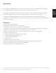
Owner's Manual


GETTING
STARTED
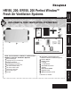
Mounting Position and Location
The HR150/ER150 and HR200/ER200 can be
suspended from exposed ceiling joists, ceiling surface
or floor mounted. (Level ventilator so drains function
correctly.)
NOTE: ER150C and ER200C are specifically designed
for installations in unconditioned spaces such as
attics and garages in regions where the outdoor
temperature does not drop below freezing. (These
units are not equipped with drain kits.)
Locate fresh air intake 6 ft (2m) or more from stale •
air exhaust to prevent exhaust air from re-entering.
Locate ventilator where length of ducting required •
is minimal.
Install HR150/ER150 and HR200/ER200 in a
conditioned space using these guidelines:
Pipe drain line (ER150C and ER200C do not have •
drain kits) from the ventilator to a drain.
Use an existing electrical outlet with appropriate •
current rating (or install one) close to ventilator
power cord.
Allow space for drain line by placing the ventilator •
at least 10 in. (254 mm) off the floor.
For access and removal of ventilator core, allow at •
least 25 in. (635 mm) of open space in front of unit.
INSULATED
FLEX DUCT
COLLAR ON
VENTILATOR
SEAL INTERIOR LINING OF
FLEX DUCT TO INSIDE COLLAR
SEAL OUTER LINING OF FLEX
DUCT TO OUTER COLLAR
M6557
Ducting
Ducting between the ventilator and the outdoors must
be insulated and have a continuous air vapor barrier.
See Fig. 4.
IMPORTANT
All ducting to the outdoors must be terminated above
anticipated snow lines and be fitted with a weather cap
that incorporates bird screening.
HR150, 200; ER150, 200 Perfect Window™ Fresh Air Ventilation Systems 68-0171—12
6
Sealing insulated duct terminations.Fig. 4.