
Manual


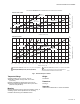
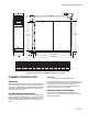
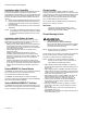


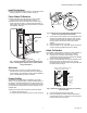
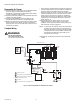
Table Of Contents
- 68-0240E-6
- 68-0240F-6.pdf
- Application
- Caractéristiques
- Fiche technique
- Planification de l’installation
- Application
- Vérifier les exigences relatives à l’installation
- Applications - appareil de refroidissement
- Applications - humidificateur
- Applications - apport d’air extérieur
- Ajout du moniteur W8600F (en option)
- Ajout de l’indicateur AIRWATCHMD W8600A
- Choix de l’emplacement
- Choix de la position d’installation
- Raccords de gaines requis
- Raccords de transition
- Déflecteurs
- Raccords de dérivation
- Installation
- Avant d’installer ce produit…
- Déballer le filtre à air électronique
- Nettoyer le compartiment du ventilateur
- Fixer le boîtier à l’appareil de chauffage
- Installer les déflecteurs
- Fixer le boîtier au système de gaines
- Sceller les joints
- Installer la clavette de la cellule dans la bonne direction.
- Fixer les poignées des cellules
- Réassembler le filtre à air
- Terminer le raccordement
- Fonctionnement
- Vérification
- Maintenance
- Nettoyage des cellules et des préfiltres
- Nettoyage des cellules dans le lave-vaisselle
- Nettoyage des cellules dans un bac
- Nettoyage des cellules dans un lave-auto
- Remise en place des préfiltres et des cellules
- Remplacement des post-filtres à fibres
- Remplacement des fils d’ionisation
- Réduction de l’odeur d’ozone
- Pièces de rechange (Tableau 3)/vue explosée (Fig. 19).
- Pièces et accessoires non illustrés (Tableau 4)
- calendrier de rappel du lavage

F300 ELECTRONIC AIR CLEANER
7 68-0240EF—06
Fig. 3. Mounting positions with variety of furnace installations.
Determine Duct Design Requirements
The air cleaner is adaptable to all new or existing forced air
heating, cooling and ventilating systems used in residential
applications. Transitions, turning vanes, or offsets may be
needed in some applications for effective operation.
Transitions
Transitions are needed when the duct is a different size than
the air cleaner cabinet. Gradual transitions reduce air
turbulence and increase efficiency. Limit expansion to no more
than 20 degrees or about 4 in. per running foot (100 mm per
300 linear mm) on each side of a transition fitting.
See Fig. 4.
Fig. 4. Change duct size gradually to minimize turbulence.
Turning Vanes
If the air cleaner is installed close to an elbow or angle fitting,
install turning vanes inside the angle to distribute airflow more
evenly across the face of the cell. See Fig. 5.
M19777
A
B
C
D
E
F
G
20 DEGREE EXPANSION PER SIDE PER
FITTING (4 in. PER LINEAR FOOT
[100 mm PER 300 LINEAR mm]).
RETURN
AIR DUCT
TRANSITION FITTING
ELECTRONIC AIR CLEANER CABINET
M5626A
CHANGE DUCT SIZE GRADUALLY TO MINIMIZE TURBULENCE.